


3
Appliance Support
The unit is supplied with 4 x Ø50mm x 400mm(L) tube incorporating
adjustable feet
Markings
Supertron on splashback
Gas cock markings indicate gas flame position
Data plate on front panel
Serial No
N.H.G.C. per burner
Test Point Pressure
Lighting Instructions
NG @ 1.0 Kpa
LPG @ 2.75Kpa
Injector
N.H.G.C.
Injector
N.H.G.C.
N.H.G.C.
2.05
22MJ/h
1.25
22MJ/h
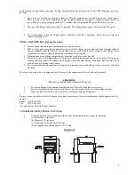
Overall Dimensions
Height
over
splashback
1130mm
Width
603mm (HC-T-600), 903mm (HC-T-900), 1203mm (HC-T-1200)
Depth
825mm
Depth (Body of Unit)
780mm
Height to Hob
900mm
Splashback
255mm x 82mm
Weight
40kg (HC-T-600), 80kg (HC-T-900), 120kg (HC-T-1200)
Gas Inlet
¾" – 20mm B.S.P. located 60mm in front rear of unit x 30mm in the
center of the unit x 70mm down beneath the body of the unit
INSTALLATION INSTRUCTIONS
(By Authotised Personnel Only)
this appliance should be installed by authorized persons only and must be installed in accordance with AG601, 1995
refer Section 5.12.4 Catering Equipment and all Clauses to 5.12.4.5.
GAS PIPING SYSTEM
Each Burners run front to rear.
The gas inlet to the appliance is located at the rear of the unit. The connection point is 425mm above the floor facing
down. The gas point is in the centre of the unit.
The unit is supplied with a ¾" B.S.P. regulator – the installer must supply a ¾" B.S.P. gas cock to enable isolation of
the appliance for servicing. The unit must have at least a 1" B.S.P. (25mm) pipe up to the connection point, with a
minimum pressure of no less than 1.13 kpa inlet. A minimum appliance operating pressure of no less than 0.1 kpa with
60% of the appliance operating. The installer must use a manometer to check the pressure and test for leaks.
Test points are provided off the Regulator control and off the gas cock manifold. Alternatively a burner injector may
be used off the top burner and the monometer tube placed firmly over the injector after removing the burner.
The appliance must be installed to local Health Dept. and gas fitting regulations.
For test point pressure settings refer to data plate on the appliance.
For Service:
call local gas agent or retailer in your region or contact manufacturer for service information, should
appliance fail to operate correctly.
Before leaving installation instruct user on the operation of the appliance, lighting of burners etc.
OPERATING AND MAINTENACNE INSTRUCTIONS, SERVICE
These instructions must be read carefully prior to initial use and retained in a safe place.
Remove all protective covering on stainless steel panels.
GRILL PLATE BURNERS, GRILL PLATE & LOWER GRILLING COMPARTMENT (Lighting Procedure)
Содержание HC-T-600
Страница 1: ...USER S GUIDE FOR GRIDDLE TOASTER...


