background image

MASTERseries - Release 7.0

29


MASTERseries Quick Start Guide

Local Management - Logging in to the FLEXmaster

Local Management - Logging in to the FLEXmaster

The following sections describe how to log in to the FLEXmaster’s command line interface (CLI).

z

Connection Requirements

z

Connecting to the FLEXmaster’s NMS Port

z

Logging In

Connection Requirements

To use the FLEXmaster’s CLI, you must have the following items:

z

Laptop

z

VT100 terminal emulation software (such as HyperTerminal) on your laptop

z

Network Management cable (NMS cable) - MASTERseries network management cable, part 
number 80001/NM

z

Ferrite bead (part number 010-0051) for NMS cable

z

USB-to-serial adapter (if your laptop does not have a DB9 RS-232 port). Refer to PTN-06-0011 
for more information.

Ferrite Bead (2-Slot Chassis)

For the 2-slot chassis, a ferrite bead (part number 010-0051) is required for the NMS cable. Under 
certain circumstances, the NMS cable can be included in ferrites with the Ethernet switch cable(s). 
See 

Ethernet Switch Cabling 

on page 19 for instructions.

Ferrite Bead (8-Slot Chassis)

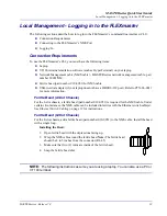
For the 8-slot chassis, add a ferrite bead (part number 010-0051) to the NMS cable. Install the bead 
with a single loop.

Installing the Bead:

1. Open ferrite bead with the depressions facing up. 
2. Wrap the NMS cable around the ferrite bead. 

Note:

 The ferrite bead 

should be 4 to 5 inches from the connector (RJ-45)

3. Make sure that two (2) turns are inside of the ferrite bead.
4. Snap the ferrite bead shut.

NOTE:  

The following instructions assume you are using a laptop. You can also use a PC or 

VT 100 terminal.

Содержание MASTER series

Страница 1: ...MASTERseries QUICK START GUIDE Part Number 002 0273 2010 Release 7 0 October 2008 ...
Страница 2: ...manual or otherwise any part of this manual or software supplied with MASTERseries for any purpose other than the purchaser s personal use without the express written permission of Turin Networks The Turin Networks Logo is a registered trademark of Turin Networks FLEXengine FLEXmaster MASTERseries and OMC Companion are trademarks of Turin Networks All other brand or product names are trademarks or...

Страница 3: ... Network Interface NI as voltage potentials as high as 300 VAC may be present across the transmit and receive pairs z Only use No 26 AWG or larger telecommunication line cord to reduce the risk of fire z Never install telephone wiring during a lightning storm z Never install telephone jacks in wet locations unless the jack is specifically designed for wet locations z Refer to the installation sect...

Страница 4: ...a wrist grounding strap and attach it to a metal part of the system unit before handling components If a wrist strap is not available maintain contact with the system unit throughout any procedure requiring ESD protection WARNING INTEGRATED CIRCUITS ICS ARE EXTREMELY SUSCEPTIBLE TO ELECTROSTATIC DISCHARGE UNLESS YOU ARE A QUALIFIED SERVICE TECHNICIAN WHO USES TOOLS AND TECHNIQUES THAT CONFORM TO A...

Страница 5: ...acking and Inspection Installation Environment 2 Slot Chassis Installation 8 Slot Chassis Installation Local Management Logging in to the FLEXmaster Connectors LEDs NOTE Multiple modules master slave functionality and E1 functionality are not supported in this release ...

Страница 6: ...be returned for any reason carefully repack equipment in the original shipping container with original packing materials if possible 6 If equipment is to be installed later replace equipment in original shipping container and store in a safe place until ready to install Installation Environment The environment in which you are installing the Adit 600 must meet the following conditions z Operating ...

Страница 7: ...r 23 inch rack NOTE Blank faceplates must be installed on each empty slot to be in compliance with product emission standards Supported Configurations The following table indicates the configurations supported by the 2 slot chassis For information about configurations supported by the 8 slot chassis see 8 Slot Chassis Installation on page 20 Double Fan Triple Fan FM16 TDM FM16 ATM FM16 PWE Total N...

Страница 8: ...ws 1 To install the unit in a 19 inch rack attach the unit with the brackets to the rack using the screws provided 2 To install the unit in a 23 inch rack remove the 19 inch mounting brackets and replace them with 23 inch mounting brackets purchased from Turin Networks 3 Ground the unit by attaching ground wire from the terminal block to the frame ground WARNING THE GROUND TERMINAL ON THE POWER BL...

Страница 9: ...lot chassis and provides instructions for installing and setting up cabling for the power supplies 24 48 VDC Power Supply FLEXmaster modules are powered by 24 48 VDC power supplies The power supplies are redundant and load sharing The LED states of the power supply are as follows NOTE MASTERseries Release 6 0 introduced a new 24 48 VDC power supply that is identified by a small white dot on the fa...

Страница 10: ...nto the empty slot and plug the fan s power connector into the power supply 3 Slide the power supply the rest of the way into the slot Press firmly to make full contact with the connector at the back of the chassis 4 Insert and tighten the screws on the front of the power supply 5 For redundant systems install a second power supply into power supply slot 1 following the same procedure except for c...

Страница 11: ... SWITCH IS OFF To connect the power leads 1 Remove the power terminal block for easier lead attachment by prying off the block with a screwdriver 2 Strip the two wires from the power source so that approximately 5 16 inch of bare wire is exposed 16 or 18 AWG insulated copper wire is recommended for power connections 3 Attach leads to the appropriate terminals using the screws on the block to secur...

Страница 12: ...and Return B Make this jumper the same gauge as the feed Attach the leads to the appropriate terminals as indicated in the diagram at the right Ferrite Bead A ferrite bead is required on the power cable Install a ferrite bead part number 010 0051 on the power cable with a loop as shown below It is recommended that the ground wire be included in the ferrite bead Earth Ground RTN A Return A 48VDC 24...

Страница 13: ...assis Installation Power Cable Routing To meet emissions standards the power cable must be routed away from all other cables connected to the chassis These include the alarm Ethernet NMS T1 E1 and V 35 cables As an example you might route the power cable as shown below ...

Страница 14: ...erminal block to secure them The alarm terminal block can be removed for easier lead attachment Plug the terminal block back into the alarm module when finished The following table describes the alarm terminal contacts Ferrite Bead Install a ferrite bead part number 010 0051 with a loop on the alarm leads as shown below Contact Alarm Description Major Alarm N C COM N O Normally Closed Common Norma...

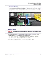
Страница 15: ...ute the alarm leads as shown below Applying Power DANGER POSSIBLE SHOCK HAZARD EXISTS PLEASE FOLLOW INSTRUCTIONS CAREFULLY After all procedures in Power Supply Installation and Cabling on page 9 and optionally Alarm Contacts on page 14 have been completed apply power as follows 1 If you have not yet done so plug the power terminal block into the power entry panel 2 Apply power to the chassis by tu...

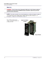
Страница 16: ...RES ARE ESSENTIAL WHEN INSTALLING AND SERVICING PARTS OR MODULES NOTE This section describes how to install application modules and adapter modules If your chassis came with modules already installed skip this section and go to Local Management Logging in to the FLEXmaster on page 29 Each module is made up of an engine or application module and an adapter module Application Module or Engine Adapte...

Страница 17: ...s attached when shipped These adapter strips are required for 8 slot chassis installation but must be removed for 2 slot chassis installation To remove the adapter strips loosen the screws holding the strips and slide the strips off the modules Re tighten the screws Bottom fixed knob Top of Module ejector handle Slide to remove ESD Adapter Strip on Adapter Module ...

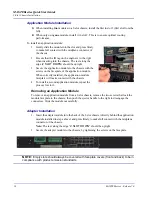
Страница 18: ...When correctly installed the application module faceplate will make contact with the chassis 4 To install a second application module repeat the process for slot 2 Removing an Application Module To remove an application module from a 2 slot chassis remove the two screws that lock the module faceplate to the chassis then push the ejector handle to the right to disengage the connectors Slide the mod...

Страница 19: ...are as follows z Up to four Ethernet cables can be grouped together within two ferrite beads z The NMS cable can be grouped with Ethernet cables up to the limit of four cables within two ferrite beads z If the installation is limited to the backhaul Ethernet and or the NMS cable a single ferrite bead with a loop can be used Note The ferrite bead should be 4 to 5 inches from the connectors Example ...

Страница 20: ... including cables is 12 inches NOTE Blank faceplates must be installed on each open slot to be in compliance with product emission standards Supported Configurations The following table indicates the configurations supported by the 8 slot chassis For information about configurations supported by the 2 slot chassis see 2 Slot Chassis Installation on page 7 FM16 TDM FM16 ATM FM16 PWE Total Number of...

Страница 21: ...lace them with 23 inch mounting brackets purchased from Turin Networks 3 Ground the unit a Connect ground wire 16 18 gauge from the ground terminal to earth ground b Connect the chassis ground screw to earth ground The chassis ground screw is the raised green screw on the side of the chassis When mid mounting the chassis you can replace this screw with a flat head screw if needed WARNING THE GROUN...

Страница 22: ...r supply 5 Install a second power supply for redundancy into power supply slot 2 as in steps 1 4 DC Power The power entry modules provide DC power protection and isolation z Each input has its own return z The recommended wire gauge for connecting power is 16 to 18 gauge NOTE When using two power supplies the input power must be connected to both A and B feeds If you only power the A feed and are ...

Страница 23: ... on the terminal block to tighten them Single Power Feed Dual Power Supplies Attach the leads to the appropriate terminal as indicated in the following diagram Secure the leads with screws on the terminal block to tighten them WARNING THE TERMINAL ON THE POWER BLOCK MUST BE CONNECTED TO THE EARTH GROUND TO PREVENT POSSIBLE DAMAGE TO THE EQUIPMENT Connect 16 18 Wire Securing Screws Gauge Wire Here ...

Страница 24: ...l block from the power entry panel 3 Strip the two wires from the power source so that approximately 5 16 inch of bare wire is exposed 16 or 18 AWG insulated copper wire is recommended for power connections 4 Insert the wires from the power source into the appropriate square holes one at a time 5 Tighten screws to clamp wires 6 Ensure that no bare wire shows after the wires are installed 7 Plug th...

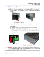
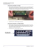
Страница 25: ...r application module and an adapter module WARNING STATIC PROTECTION IS REQUIRED DURING INSTALLATION PROPER HANDLING GROUNDING AND PRECAUTIONARY ESD MEASURES ARE ESSENTIAL WHEN INSTALLING AND SERVICING PARTS OR MODULES Adapter Strip Installation To be compliant with EMI an adapter strip must be installed on the engine and adapter modules in an 8 slot chassis Typically adapter strips are shipped at...

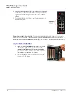
Страница 26: ... of the adapter strip to fit under the screw heads 2 Tighten the screws to hold the adapter strip in place Adapter Strip Installation on Adapter Module 1 Slide the adapter strip under the screw heads until snug Spacers below the screw heads allow enough space to install the adapter strip without loosening the screws If the screws have been driven tight to the panel loosen them enough to allow the ...

Страница 27: ...s recommended to install it into slot 1 first slot from the left 1 Gently slide the application module into slot 1 and press firmly to make full contact with the midplane connector of the chassis Master Module The master module configures the rest of the modules slaves When installing modules into the 8 slot chassis insert a module and when this module has completed its initialization link LEDs sh...

Страница 28: ...lication module from an 8 slot chassis remove the two screws that lock the module faceplate to the 8 slot chassis then lift up on the ejector handle labeled with the module name to disengage the connectors Slide the module out carefully Adapter Module Installation 1 Insert the adapter module into the back of the 8 slot chassis directly behind the application module installed using the application ...

Страница 29: ...top does not have a DB9 RS 232 port Refer to PTN 06 0011 for more information Ferrite Bead 2 Slot Chassis For the 2 slot chassis a ferrite bead part number 010 0051 is required for the NMS cable Under certain circumstances the NMS cable can be included in ferrites with the Ethernet switch cable s See Ethernet Switch Cabling on page 19 for instructions Ferrite Bead 8 Slot Chassis For the 8 slot cha...

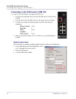
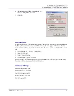
Страница 30: ...ble into the serial port on your laptop 3 Launch your terminal emulation program and set the following port parameters Bits per Second 9600 Data bits 8 Parity None Stop Bits 1 Flow Control None 4 Make sure that the emulation is set to VT100 in your terminal emulation program HyperTerminal Users Turin Networks recommends modifying HyperTerminal settings as described below 1 From within the HyperTer...

Страница 31: ...baud using the same approach If there is a baud rate mismatch between Procomm and the master module the master module could reboot To prevent this 1 Go to Options Data Options Setup Files 2 Select the Data tab 3 Select Terminal Options 4 Set the Enquiry Type field to OFF Other versions of Procomm might require you to navigate to the Enquiry Type field differently Consult your Procomm manual for mo...

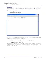
Страница 32: ...n to the FLEXmaster you start in the root mode of the command line interface CLI At this point you can issue commands through the CLI Note You may see one of the following messages immediately upon logging in Unable to open userid file Problem reading userid file The admin user can still log in You can correct this situation by adding modifying or deleting users For information about these command...

Страница 33: ... is a RJ 45 connector with the following pinouts NOTE A ferrite bead is required on this cable see Ferrite Bead on page 15 for further information Pin Name Description 1 Receive Receive from network 2 Receive Receive from network 3 Transmit Transmit to network 4 5 N C Not connected 6 Transmit Transmit to network 7 8 N C Not connected Pin Name Description 1 N C Not connected 2 Tx Data Transmit Data...

Страница 34: ...2 Transmit Data A 15 Receive Clock A 3 Receive Data A 16 Receive Data B 4 RTS 17 Receive Clock B 5 CTS 18 Open Pins No Contact 6 DSR 19 Open Pins No Contact 7 Signal Ground 20 DTR 8 CD RLSD 21 Open Pins No Contact 9 Open Pins No Contact 22 N C Not Connected 10 Xmit Clock A 23 Xmit Clock B 11 External Clock A 24 External Clock B 12 N C Not Connected 25 N C Not Connected 13 Open Pins No Contact 26 O...

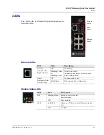
Страница 35: ...ivity Blinking Yellow or Blinking Green Activity on circuit Connector may have a yellow or green LED at this position Status Bottom in 8 slot Left in 2 slot Off No connection to port Solid Green Port connected to a valid source LED State Description PST Flashing Green Passed power system test Master module Off Slave module ALM Solid Red Alarm on a T1 E1 port or failed power system test Off No alar...

Страница 36: ... LED State Description FM16 1 16 Solid Red OOF Out of Frame or AIS Solid Green Normal link is up Flashing Red LOS Loss of Signal Solid Yellow Yellow sync alarm or RAI Indicates red alarm on the far end Flashing alternating Yellow and Green Loopback in progress Off Link is disabled ...

Отзывы: