


2
www.turck.com
• 1-800-544-7769 • Fax:
(763)
553-0708 • TURCK • Minneapolis,
MN
55441
www.turck.com
• 1-800-544-7769 • Fax: (763) 553-0708 • TURCK • Minneapolis, MN 55441
3
INTRODUCTION
panner module FDN-DN1 provides means to
transfer data between two DeviceNet networks. The
module supports three standard I/O connections:
Poll, COS and Cyclic. Communication speed (Data Rate) is
determined during power-up sequence, through
“Autobaud” mechanism. Spanner consists of two optically
isolated nodes referred to as “Node A”, and “Node B”, each
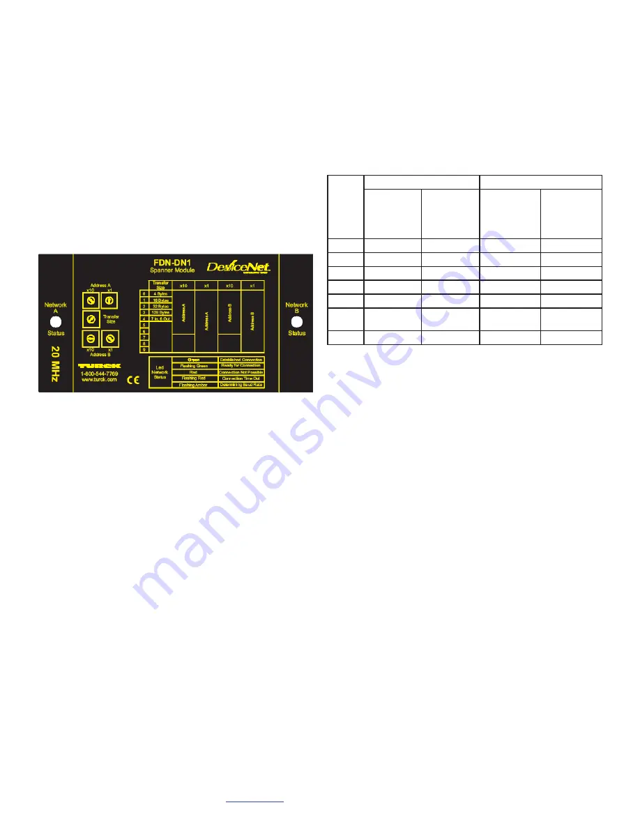
residing on different networks. Module nameplate, as
shown on Figure 1, describes rotary switch functions and
available setup options.
NODE ADDRESS SWITCHES
Module has two pairs of address switches marked as
“Address A” and “Address B”. Switch marked as “x1” sets
unit address 1, …, 9 or 0. This switch corresponds to a
least significant decimal digit. Switch marked as “x10” sets
decimal ten’s address and corresponds to most significant
decimal digit. Following positions are valid: 0, 1, 2, 3,
4, 5, or 6 that correspond to addresses 0, 10, 20, 30, 40,
50 or 60. When node A “X10” switch is set to position 7,
it indicates that node A (only) address is programmable.
Node commissioning in this case, sets the node address.
Positions 8 and 9 are reserved and not used. Spanner must
be powered from network “A” through node “A” connector
to communicate. Node “B” physical layer is powered from
network “B”. If network B stays without power, all data from
node B defaults to 0 value and node “B” LED turns red.
Transfer Size Switch
Transfer Size Switch is a single switch that determines the
size of I/O data of both nodes A and B. Switch positions
0-4 set I/O data size of the Spanner to fixed value. Position
4 refers to backward compatibility with CDN-SM-0020
module. Position 5 is used for setting user defined
data size.
Switch
Position
Node A
Node B
Produced
Data (Rx)
Input Data
(Bytes)
Consumed
Data (Tx)
Output Data
(Bytes)
Produced
Data (Rx)
Input Data
(Bytes)
Consumed
Data (Tx)
Output Data
(Bytes)
0
4
4
4
4
1
16
16
16
16
2
32
32
32
32
3
128
128
128
128
4
7
6
7
6
5
Programmable
0 - 128
Programmable
0 - 128
Programmable
0 - 128
Programmable
0 - 128
Example
21
3
3
21
Note:
Example in the above table shows the use of software settable
(programmable) I/O data size. The following rule applies to
mapping of spanner module, when Transfer Size Switch is set
to position 5:
• Input data size of node A = Output data size of node B
• Output data size of node A = Input data size of node B
Factory Defaults
Device comes out of box preset as follows:
• Address Switches: 0 (side A); 1 (side B)
• Data Size: 4 bytes
• Data Rate: autobaud
Power cycle
To change default values, use rotary switches or network
configuration tool and EDS file. In any case, it is necessary to
cycle power of the module to make a change permanent.
Figure 1. Device Label
S


