


7
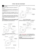
Fitting the Straight Gate
Even though possible to mount the Straight gate in both
directions, it is suggested that the Butterfly valve pins (Figure 8)
are facing towards the exhaust exit.
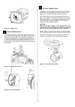
Prior to mounting the Straight Gate, place v-band (Figure 10)
over weld on flange by unscrewing the nut on the v-band as far
out as possible and then squeezing the bolt in a syringe motion
to expand the v-band (squeeze the dots together below). Once
the v-band is in its fully expanded position, slide the v-band over
the flange to allow for the wastegate to be installed.
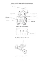
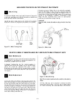
Figure 8
– Butterfly Valve Pins
Using the 3/8” deep socket and a torque wrench Tighten the V-
Band to 7N.m (5 ft/lbs). Ensure the wastegate is home correctly
while torquing the nut to not have a false torque as this will likely
contribute to exhaust leaks.
It is important that the butterfly valve sits slightly open for
installation. This allows for no interference during the installation
process. This can be adjusted via the manual override. (Figure
9)
Figure 9
– Manual Override
Figure 10
– V Band Clamp
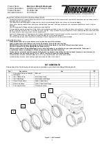
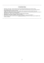
Figure 11
– Exploded drawing of assembly of Electronic Straight
Gate.
2
3
Manual
override
Valve Pins


