


11
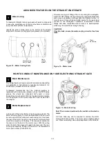
Figure 16
– Water Lines
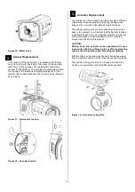
Sensor Replacement
In the event that the sensor fails, it is located under the top
cap, it is held on with two 2.5mm Allen keys for the cap and
two 2.5mm for the encoder. The replacement sensor part
number (TS-0550-3123). The encoder is located under neath
the top cap of the Electronic straight gate.(Figure 18 ) the
grommet will remain attached to the top cap and be removed
as one piece
Figure 17
– Removal of top cap
Figure 18
– Encoder location
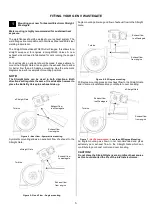
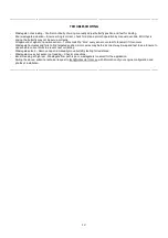
Actuator Replacement
The actuator can be removed and rotated through 3 different
orientations; these are parallel to the body, 30 deg to the
body and the current configuration 90 deg to the body.
The actuator locking pins are 3mm Allen keys that lock the
body to the actuator. It is important that the butterfly remains
in the same position, the recommended position is to be just
off the valve seat. It is also advisable to not to move the
manual override during this process.
CAUTION!
Moving body and actuator while separated will cause
issues with calibration. If moving to one of three mounting
options observe positions before moving readjusting.
With the Allen key pins removed the body can be separated
from the actuator and one of the three options can be picked.
The actuator locking pins are to be Torqued to 6N/mm as
well as a new application of Loctite 243 is also required.
Figure 19
– Actuator Locking Pins
3
4


