3
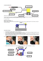
Put the V-Band clamp over the adapter before re-installing the O-Ring seal and the Race Port
Open the V-Band clamp and place in position. Tighten the V-Band clamp screw until it is finger tight then turn an additional 2.5
turns or 4 Nm (3 ft/lbs) with an allen key. Be sure not to over tighten the screw as this will cause damage to the V-Band clamp
Install the provided provided nipple into one of the ports in the top cap and install the blanking plug into the other.
Connect Port 2 of the solenoid to the pressure nipple of the Race Port BOV.
Secure all silicone hose ends with correct clamps
Start the engine and check for air leaks in the system
THROTTLE POSITION CONNECTION
The BOV controller can be wired to the existing throttle position sensor on your vehicle. Connect the white wire to the signal output wire
from the existing throttle position sensor.
(OPTIONAL)
For vehicles without a standard throttle position sensor (such as the 12V Cummins Diesel engine), an external one can be
wired in. The
ORANGE AND GREEN
must be used to power the external throttle position sensor if one needs to be installed as the
TPS requires a 5V power supply and not a 12V power supply.
SWITCHED INPUT CONNECTION (OPTIONAL)
If your vehicle does not have a standard throttle position sensor and you do not want to install an external throttle position sensor, a
double throw switch can be used to activate the BOV. The switch needs to ground the
GREY WIRE ONLY
when the accelerator pedal
is pressed in and needs to ground the
BROWN WIRE ONLY
when the accelerator pedal is released.
ADJUSTING YOUR BOV CONTROLLER
DURATION:
The duration is the length of time that the solenoid blocks the pressure signal to the BOV. The longer the duration, the
longer the BOV will not have pressure supplied to the cap, essentially keeping the BOV open. The controller also has an override
function which reactivates the BOV once it detects positive throttle movement, independent of what the duration is set at.
SENSITIVITY:
The sensitivity setting determines how the BOV controller reacts to throttle movement. The controller will only activate on
negative changes in throttle. The higher the sensitivity setting, the lower the negative change in throttle movement needs to be before
the solenoid will activate the BOV e.g. a change from 4V to 3.5V will not activate the valve but from 4V to 3V will activate the valve.
(OPTIONAL IF SWITCHED INPUT CONNECTION METHOD IS NOT USED) ENABLE FUNCTION:
Grounding the
BROWN WIRE
activates the enable function which allows the BOV controller to keep the solenoid activated. Even though the unit is still reading
changes in throttle position, it will not respond to them, not allowing pressure to reach the top of the BOV. The yellow LED will stay on
when this function is activated. This function can be used to limit boost as the BOV will not have any pressure keeping it closed. It can
also be used as an over boost safety feature when connected to another device such as a data logger or ECU which can ground the
wire if a over boost scenario is reached.
(OPTIONAL IF SWITCHED INPUT CONNECTION METHOD IS NOT USED) DISABLE FUNCTION:
Grounding the
GREY WIRE
will
activate the disable function which disables the BOV controller. The BOV controller is still switched on but will not respond to changes in
throttle position, keeping pressure to the top of the BOV, not allowing the BOV open. This can be used when the BOV is not required to
be functional e.g. when using cruise control, the BOV will not actuate on sudden throttle changes cresting hills.
RACE PORT SPRING REPLACEMENT (OPTIONAL)
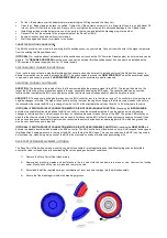
The Race Port is fitted with an orange inner spring which is suitable for most applications but additional springs can be installed to
ensure the valve is closed if you are experiencing the valve opening under boost conditions.
1)
Remove the Race Port off the intake piping
2)
Remove any pressure nipples and port blanks in the top cap. Hold the cap down in a press or vice. Unscrew the locking
collar. Slowly, back off the vice or press and remove the cap.
3)
Select and install the required spring or combination of inner and outer springs into the piston assembly.
4)
Ensure that the diaphragm is inside the diaphragm groove.


