Turbo Air ADR043AE Скачать руководство пользователя страница 1

Turbo air Speeds Up the Pace of Innovation 


Part No. KUCTB2504 

September 2020 edition


Refrigeration System 

Installation & Operation Manual 

Please read this manual completely before attempting to install or operate this equipment ! 
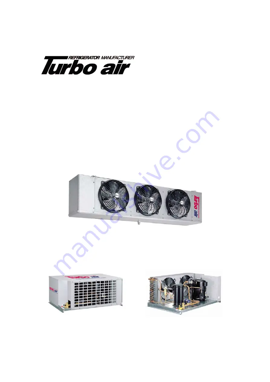


Unit Cooler   


Condensing Unit 


Содержание ADR043AE

Страница 1: ...ce of Innovation Part No KUCTB2504 September 2020 edition Refrigeration System Installation Operation Manual Please read this manual completely before attempting to install or operate this equipment U...

Страница 2: ...Inspection 3 Locating Unit Cooler 4 Unit Cooler Piping 6 Expansion Valve Selection 8 Defrost 11 Locating and Mounting Condensing Unit 14 System Operation 16 Unit Cooler Troubleshooting 19 System Trou...

Страница 3: ...o prevent electric shock Please call the specialized installation company or trained personnel when you installing moving operating of the unit Field wiring must confirm to the requirements of units e...

Страница 4: ...ded location methods of Unit Cooler 1 Avoid placing Unit Cooler close to doors Install like Figure 3 or Figure 4 2 Avoid having them face each other when installing multiple units Install like Figure...

Страница 5: ...rea above the unit cooler must be sealed or exposed in such away to allow hand cleaning without the use of tools When lagging or bolting unit flush to the ceilings seal the joint between the top and t...

Страница 6: ...ing installation of the piping to prevent entrance of foreign matter Use only refrigeration grade copper tubing properly sealed against contamination Figure 8 Suction piping installation on an evapora...

Страница 7: ...gh walls or ceilings Precautions should be taken to see that the piping does not touch any structural the transmission of vibration into the building The piping chase must be thoroughly sealed to prot...

Страница 8: ...SBFDE A C ADR171AE 17213 SBFSE B C SBFDE A C ADR191AE 19213 SBFSE B C SBFDE A C ADR258AE 25883 SBFSE B C SBFDE B C ADR325AE 32584 SBFSE C C SBFDE B C ADR352AE 35287 SBFSE C C SBFDE B C ADR392AE 39317...

Страница 9: ...56BE 15793 SBFSE B Z SBFDE A Z TCE175BE 17697 SBFSE B Z SBFDE A Z TCE214BE 21415 SBFSE C Z SBFDE B Z TCE241BE 24247 SBFSE C Z SBFDE B Z TCE288BE 28959 SBFSE C Z SBFDE C Z TCE325BE 32738 SBFSE C Z SBFD...

Страница 10: ...00 150 30 75 100 150 30 75 100 150 30 75 100 150 3000 1 2 5 8 5 8 5 8 1 2 5 8 5 8 7 8 5 8 5 8 7 8 7 8 3 8 3 8 3 8 3 8 4000 1 2 5 8 5 8 5 8 5 8 5 8 7 8 7 8 5 8 5 8 7 8 7 8 3 8 3 8 3 8 3 8 6000 5 8 7 8...

Страница 11: ...r may be adequate to keep the evaporator coil clear of frost In other applications a defrost timer may be necessary to help assure a clear coil in a medium temperature environment Air defrost is initi...

Страница 12: ...mination time adjust the position of thermostat If this method is used it will result in higher temperature Adjustable Type F25 Series The F25 Control terminates defrost and delays evaporator fan oper...

Страница 13: ...ntacts between terminals 2 and 4 are normally closed when timer is energized and open during a defrost to de energize refrigeration and fans Setting Defrost Initiation Time Move a white tab tripper on...

Страница 14: ...saves energy in low ambient conditions Fan speed controller keeps the condensing pressure at a steady level by regulating the speed of the AC EC fan motors When pressure is declining the controller d...

Страница 15: ...ts Spring Mounted Compressor Semi hermetic compressor unit use the mounting assembly shown in Figure 11 the shipping spacer is to be in place during shipment to insure maximum support for the compress...

Страница 16: ...djusting the expansion valve Evaporator superheat greater than 14 can substantially reduce system capacity while superheat less than 4 has the potential for flood back Compressor Superheat Compressor...

Страница 17: ...ne in the high side only and with liquid metering devices If R 404A is used liquid must be charged and read up refrigerant explanatory Start up Use the following operating procedure after the installa...

Страница 18: ...on the high pressure side it is necessary to check the system so be sure to reset the system after visiting the site Turbo air applied a manual reset method to protect the system Refer to the followin...

Страница 19: ...Ice build up in coil quickly Fin spaced too narrow Replace coil Evaporating temperature too low Adjust expansion valve Decrease of air volume Check fan and clean air filter Unit cooler capacity is too...

Страница 20: ...cle too short Adjust defrost thermostat or timer for longer cycle Defective timer or defrost thermostat Replace defective component Ice accumulating on ceiling around evaporator on fan guard or blades...

Страница 21: ...ne solenoid not open Repair or replace coil Noisy Compressor Flooding of liquid refrigerant into crankcase Check expansion valve setting Improper piping support on suction or liquid line Relocate add...

Страница 22: ...itions are within allowable limits Discharge valve partially closed Open valve Dirty condenser coil Clean coil Overcharged refrigerant Reduce charge Compressor loses oil Lack of refrigerant Check for...

Страница 23: ...23 Field Wiring Diagram 1 Typical wiring diagram for single evaporator with or without defrost timer...

Страница 24: ...24 Diagram 2 Typical diagram for single evaporator defrost timer only Diagram 3 Typical diagram for single evaporator with defrost timer and single phase heater contactor...

Страница 25: ...25 Diagram 4 Typical diagram for single evaporator with defrost timer and 3 phase heater contactor Diagram 5 Typical diagram for single evaporator defrost timer only TTE TYPE...

Страница 26: ...26 4184E Conant street Long Beach CA 90808 FAX 310 900 1008 Toll Free 888 900 1002 U S A Canada http www turboairinc net...

Отзывы: