6
C. DRUM SECTION
DISASSEMBLY
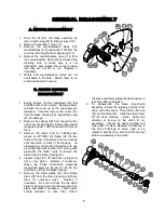
1. To remove the drum, first disconnect the cable
from the u-bolt (43) and lay aside. If removing
the drum from the motor end with the motor
and brake disassembled, first remove the
eight capscrews (51), eight roll pins (103), and
air cylinders covers (96,97) on the air cylinders
(17 & 125).
Note: you
may need to remove
the air lines. Mark them for re-assembly.
2. You will need to support the weight of the
drum with a hoist. Remove the four capscrews
(70) and the nuts and washers (71, 72) on the
bottom of the brake housing, (16). At this time
you will need to remove two capscrews (91),
nut and washers (85, 86) from the frames (73
or 74). Do not remove air cylinder (76) yet.
Disconnect the air line from the backside of
the brake housing (16) that goes to the band
brake cylinder. If a complete tear down is not
necessary, make sure the output shaft (20) or
input shaft (21) does not move during removal
of the drum. With help from a hoist or another
person, slide the whole brake housing out
from the drum until you are free of everything.
You can now remove the brake band
assembly (77). Note which frame the
mounting bolts are on for re-assembly.
Inspect and replace any worn parts of this
assembly. Remove the outer thrust collar
(131) by removing two set screws (130).
3.
Remove the thrust ring (128) and clutch plate
(15) by removing six capscrews (129).
Remove the sliding clutch (13), coupler (12),
keys (47) and the inner thrust collar (46).
Remove the drum using a hoist. Inspect the
bushings (19) in both ends of the drum.
Note:
You may also inspect the bushing and seal
(40, 41) that are located in the end of the
brake housing.
4.
Inspect or replace the drum clutch (14) at this
time by removing six capscrews (45). If you
replace the clutch, make sure to torque the
capscrews to the specified torque upon re-
assembly.
D. GEAR SECTION
DISASSEMBLY
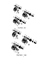
1. Drain the oil at the bottom of the gear housing
by removing the plug (31).
2. To disassemble the gear section, you must
start with the outer cover. Remove the
capscrews (30) and cover (3A).
Note: If you
have the blocked piston cover assembly, take
it off as an assembly and see Service of
Blocked Piston Cover Assembly.
3. Inspect the o-ring (33), bearing (27), and
spacer (127). Remove and inspect the outer
thrust washer (34) and replace if necessary.
4. Remove input gear set (22A), the inner thrust
washer (34), sun gear (7), and the secondary
gear set (23). Remove the thrust washer (37)
and inspect for wear. Replace if necessary.
5.
Remove the primary housing (9) by removing
eight capscrews (35).
Note: The housing is
very heavy. Use caution when removing it.
6. After removing the primary housing, inspect
the o-ring (36). Remove the sun gears (8
,111). Rotate thrust washer ((24-5) or (24-7))
into alignment with snap ring ((24-9) or (24-8)).
Remove snap ring from groove on shaft (20).
Remove output gear set (24). Remove and
inspect the thrust washer (38). Replace if
necessary.
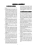
E. PLANET SET DISASSEMBLY
1. Remove the retaining rings from the planet
pins.
2. Remove the pins from the carrier by carefully
tapping them out.
3. Remove the planet gears, thrust washers and
bearings from the carriers.
4. Inspect the pins, bearings, and gear bores for
evidence of wear and replace if necessary.
5. To
re-assemble
output gear set first insert
snap ring.
6. Next insert thrust plate into carrier of input or
output gear set along with gears, bearings and
washers.
7. Being careful to line up the planet pins with the
thrust washers and bearings. Press the pin
into the carrier. If the pins are not lined up
properly, the thrust washer can be shattered
during the pressing operation.
8. Replace retaining rings.
Содержание Rufnek 100
Страница 7: ...7...
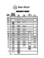
Страница 20: ...19 VISCOSITY CHART...
Страница 22: ...21 TWG PO Box 1130 Jenks OK 74037 1130 USA Phone 918 298 8300 www dovertwg com...


