5
GENERAL DISASSEMBLY
A. MOTOR DISASSEMBLY
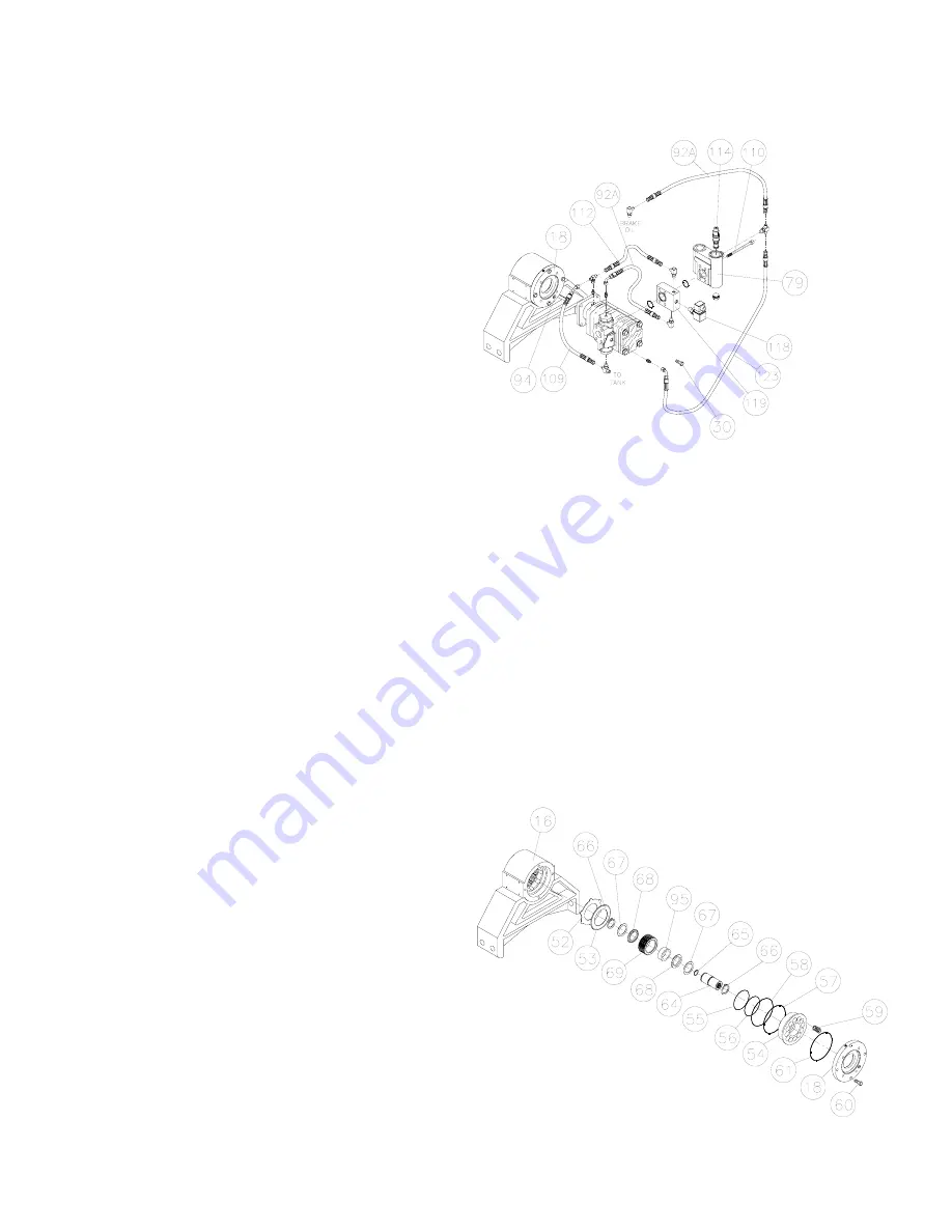
1. Drain the oil from the brake assembly by
removing the plug (94) from brake cover (18).
2. Remove hoses (92A, 109 & 112).
3. Remove the counterbalance block (79);
manifold block (119) and switch (118) from the
motor by removing the four capscrews (110).
4. Remove the counterbalance valve (114) from
the counterbalance block (79) and inspect the
metering hole to make sure it is not
obstructed. Also, inspect the o-rings to insure
that they are not flat or cut. Replace if
necessary.
5. Motors and counterbalance valves are not
serviceable in the field. Return them to an
authorized dealer for service.
B. BRAKE SECTION
DISASSEMBLY
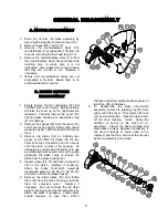
1. Evenly remove the four capscrews (60) that
hold the brake cover in place. Spring pressure
will raise the cover up as the capscrews are
loosened. Carefully remove the cover (18)
from the brake housing (16). Inspect the o-ring
(61) for damage.
2. Remove the springs (59) from the piston (54)
and check the free height. Each spring should
measure at least 1.200 inches with no force on
them.
3. Remove the piston (54) by installing two
pieces of 3/8”-16NC all thread into the two
holes in the top of the piston and run in evenly
until the piston is clear of the housing. An
alternate way of removing the piston is to use
a portable hydraulic power unit or air to gently
pressurize the brake cavity to remove the
piston from the brake housing (16).
4. Inspect o-rings (55, 57) and back up rings (56,
58) on the piston. Replace if necessary.
Grasp the brake driver/clutch assembly
(assembled items 64, 65, 66, 67, 68, 69, 95)
and remove it from the brake housing.
5. Remove the stator plates (52) and friction
discs (53) from the brake housing and check
them for excessive wear. Replace if
necessary. Be sure to check the top stator
plate for scoring caused by the removal of the
piston and polish if necessary. Friction discs
should measure no less than .055-in.
thickness and stator plates should measure no
less than .068-in thickness.
6. To disassemble the brake driver/clutch
assembly, remove the retaining ring (66) from
either end of the driver. Then remove the race
(67) and bushing (68). Slide the brake driver
off the drive coupling.
(Note:
Notice the
direction of lock-up on the clutch for re-
assembly).
Inspect the driver coupling and
brake driver for wear. Replace if necessary. If
the drum bushings or seals need to be
replaced, see the drum section of this manual
before re-assembly of the brake.
Содержание Rufnek 100
Страница 7: ...7...
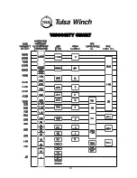
Страница 20: ...19 VISCOSITY CHART...
Страница 22: ...21 TWG PO Box 1130 Jenks OK 74037 1130 USA Phone 918 298 8300 www dovertwg com...


