background image

Gigant sweeping machine

  25

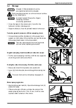
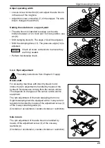
Adjust operating width

•  Loosen screw connection (6) and adjust the side broom 

in the area of the longhole.

•  Adjust the screw connection (7) of the stopper. The side 

broom changes the width (5).

Setting the side broom - support point

•  The side broom is intended to sweep out the side 

borders between a 12 o'clock and 3 o'clock position; see 

arc (8).

•  Shift clamping discs (9). The angle (10) will be adjusted.
•  Shift the clamping discs (11). The pressure angle (12) is 

adjusted.

Check all screw connections to ensure they 

are irmly seated.

•  Perform functionality check.

3.4.4  Rpm adjustment

The safety instructions from Chapter 3.3 apply.

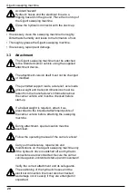
Brush shaft

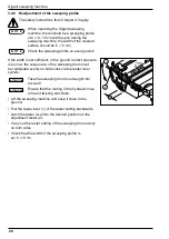
For sweeping machines with direct hydraulic motor 

intake, the rpm adjustment is handled by means of the 

hydraulic luid pressure coming from the carrier vehicle. 

This depends on the types of the carrier vehicle and its 

equipment.
The rpm adjustment of the main sweeping drum on a 

Gigant sweeping machine equipped with a 3-way current 

regulator is handled by means of the adjustment screw (1) 

of the 3-way current regulator (2).
(Clockwise = acceleration, counter-clockwise = restriction)

Side broom

The rpm adjustment of the side broom is handled by 

means of the adjustment screw (3) of the one-way 

restrictor (4).
(Clockwise = acceleration, counter-clockwise = restriction)

ATTENTION

Содержание Profi Gigant

Страница 1: ...Profi Gigant Sweeping Machine Operating Manual ...

Страница 2: ......

Страница 3: ...iliarise with the use of the machine and its service and maintenance The manual also helps you to avoid dangers and damage We wish you optimum results with your Proi Gigant sweeping machine Tuchel Maschinenbau GmbH This operating manual is current as of January 2012 Our continuous efforts towards an improvement of the Proi Gigant sweeping machine may lead to changes in detail The introduction of i...

Страница 4: ...Preface 4 ...

Страница 5: ... 15 2 9 Warning images on the machine according to ISO 11684 16 3 Gigant sweeping machine 17 3 1 Description of the product and accessories 17 3 2 Storage 19 3 3 Attachment 20 3 3 1 Initial attachment 21 3 3 2 Quick change receptacle 21 3 3 3 3 point linkage 22 3 4 Operation 23 3 4 1 Transport trips 23 3 4 2 Start up 23 3 4 3 Side broom adjustment readjustment 24 3 4 4 Rpm adjustment 25 3 4 5 Empt...

Страница 6: ...Table of contents 6 ...

Страница 7: ...thus suitable for cleaning large irm surfaces The various additional accessories such as the dirt collection vessel with an integrated 3rd and 4th support wheel the water spraying device for dust suppression a side broom for close to the border sweeping a hydraulic side adjustment to ease work etc make it possible to adapt the Gigant sweeping machine to the most widely varied working environments ...

Страница 8: ...able sweeper the harmonised European standards DIN EN 292 1 2 DIN EN 982 DIN pr EN 1553 and DIN EN 474 1 2 were also applied This is documented in the EU declaration of conformity 1 2 5 Speciications for enquiries and orders When ordering spare parts or accessories please specify the type label serial number and the year of construction of the Gigant sweeping machine Original accessories original ...

Страница 9: ...vehicle Its purpose is to clean irm surfaces with normal dirt build up If the machine is used for a purpose different from the one above we as the manufacturer do not take any responsibility for the safety the risk in this respect rests entirely with the user Proper usage includes observance of the operating maintenance and service conditions that we prescribe as well as relevant speciications SA ...

Страница 10: ...rating width A total width mm 2600 2860 2900 3250 3200 3550 3500 3850 B Operating width if positioned at an angle of 20 mm 2360 2630 2900 3170 Weight of basic machine kg 1200 1250 1300 1350 Weight of basic machine collector vessel kg 1650 1700 1760 1820 Dirt collection vessel volume kg 760 850 935 1025 Sweeping drum side broom mm 800 550 800 550 800 550 800 550 Oil quantity required at 160 bar l m...

Страница 11: ...n warning about injuries resulting from cuts Safety notices whose non observance create hazards for the machine and its functionality have the word attached Notices are labelled as follows Safety signs that are directly attached to the machine must deinitely be adhered to and must be kept in a fully legible state 2 2 Qualiication and training of personnel The Gigant sweeping machine must only be u...

Страница 12: ...afety notices listed in this operating manual current national accident avoidance regulations as well as company internal regulations governing work operation and safety that apply must be followed The accident insurance regulations governing safety at work and accident avoidance are binding Observe the safety notes of the vehicle manufacturer When operating on public roads the appropriate legal r...

Страница 13: ... possible damage prior to start up The positioning of the hydraulic hoses must also be checked as damages occur easily if hydraulic hoses are entangled or squashed During detachment the supports must be put into their respective position Check the immediate area before starting to drive and before start up e g for children Ensure that there is suficient visibility No person may be present in the w...

Страница 14: ...and when driving parallel to a slope Pay attention to the inluence of the attached Gigant sweeping machine on driving behaviour and steering and braking ability The hydraulic swivel mechanism for swivelling the sweeping machine must only be operated if no persons are present in the area of rotation Deinstallation After switching off the device there is danger due to the continued movement of the c...

Страница 15: ... the sweeping drum and sweeping rail Lawfully dispose of oil and grease Directly after inishing work all protection equipment must be reattached Before restarting the points listed in the sections on start up must be adhered to 2 7 Unauthorised conversion and spare parts manufacturing Conversion of or changes to the machine are only permitted after consultation with the manufacturer Original spare...

Страница 16: ...as long as parts may move Article no 00 KC 00101 Do not touch any moving machine parts Wait until they have come to a complete standstill Article no 00 KC 00102 When lowering the Gigant sweeping machine keep suficient distance Article no 00 KC 00103 Do not stand in the rotation area during operation Article no 00 KC 00100 Keep all labels clean at all times Missing or damaged labels must be replace...

Страница 17: ...ehicle The sweeping drum standard equipment includes Beeline brush rings made from 100 PP The brush rings are 800 mm in diameter The dirt collection vessel is opened and closed via the actuation of two hydraulic cylinders Actuation is initiated from the carrier vehicle The wear resistant Vulkollan rail is connected to the lower edge of the dirt collection vessel along its entire length to guide th...

Страница 18: ...raulic cylinders A double acting hydraulic control circuit is necessary on the carrier vehicle Hydr side broom close to the border sweeping with rpm regulation StVZO German vehicle licensing regulations approved equipment consisting of warning lags and contour illumination According to StVZO stipulations both are prescribed and must be used for travelling on public roads 3rd and 4th support wheels...

Страница 19: ...ition Take the sweeping drum s net weight into account when adjusting the levers Gigant sweeping machine without collector vessel For the open sweeping machine shift the two supports 5 to the ground and secure them Swing the side broom away from the work area Move side broom from position A to position B Lever 6 locks the side broom through the locking bar 7 The lever 6 must be completely engaged ...

Страница 20: ...s gross weight and transport dimensions must be taken from the manufacturer s information about the carrier vehicle and must be checked before start up If a ballast weight is required attach it as prescribed to the intended attachment points of the carrier vehicle before attaching the sweeping machine During attachment special caution must be exercised Follow the operating manual of the carrier ve...

Страница 21: ...ey and secure the carrier vehicle against unintended start up and movement Check the receptacle for soiling Clean if necessary Drive the carrier vehicle to within 300 mm of the Gigant sweeping machine Lower the receptacle bolt of the carrier vehicle until below the receptacle openings 1 of the Gigant sweeping machine Approach with the carrier vehicle and raise the lifting gear Insert the locking b...

Страница 22: ... vehicle manufacturer and secure with spring plug Select bolt diameter 3 or 4 according to the attachment category and secure with spring plug 5 Hook the upper hook and secure according to the speciications of the vehicle manufacturer The upper hook is to be set so that the attachment receptacle is perpendicular to the ground Verify the correct seating of the attachment receptacle Connect the hydr...

Страница 23: ...p The safety instructions from Chapter 3 3 apply For the open sweeping Gigant sweeping machine shift the two supports upwards and secure them Open the tap of the hydraulic cylinder of the collector vessel emptying mechanism and side broom The maximum driving and sweeping speed is 6 km h When operating the sweeping machine a sweeping proile of 6 to 10 cm appears See Chapter 3 4 8 for adjustment of ...

Страница 24: ...f the vehicle until the attachment support 2 with the support roll carrier is positioned in the centre of the roller guide 3 Height indicator with the green caps 4 are at the same height 0 Now check again that the height indicator of the receptacle and the height indicator of the swivel element are at the same angle 0 in relation to each other can be better recognised from the side of the sweeping...

Страница 25: ...nality check 3 4 4 Rpm adjustment The safety instructions from Chapter 3 3 apply Brush shaft For sweeping machines with direct hydraulic motor intake the rpm adjustment is handled by means of the hydraulic luid pressure coming from the carrier vehicle This depends on the types of the carrier vehicle and its equipment The rpm adjustment of the main sweeping drum on a Gigant sweeping machine equippe...

Страница 26: ...r vehicle If the swept material is wet it may be useful to actuate the control lever briely several times to facilitate emptying 3 4 6 Open sweeping The safety instructions from Chapter 3 3 apply Lift the Gigant sweeping machine and keep it close to the ground Flip the respective control lever for the sweeping machine hydraulics in the carrier vehicle The direction of low is changed Fully open the...

Страница 27: ...g angle is attained by rotating the machine around the pivot point Once the sweeping angle has been set push the locking bolt 3 into the intended drill hole and secure it with the spring plug 2 Overload protection The safety instructions from Chapter 3 3 apply To protect against overload upon encountering an obstruction when starting to drive the adjustment bar 1 is secured by means of the locking...

Страница 28: ... is too low the suspension of the sweeping drum must be readjusted evenly on both sides via the raster lever system Take the sweeping drum s net weight into account Ensure that the routing of the hydraulic lines is free of twisting and kinks Lift the sweeping machine and keep it close to the ground Pull the raster lever 1 of the raster setting backwards Latch the raster level into the desired posi...

Страница 29: ... Lower the sweeping machine until the castor wheels touch the ground The castor wheels point toward the carrier vehicle Deinstall the sweeping machine with the dirt collection vessel closed and empty Close the tap for the hydraulic cylinder for drainage Close side broom tap Tilt the side broom upwards and secure it see Chapter 3 4 Transport trips For the open sweeping Gigant sweeping machine shift...

Страница 30: ...t is located beneath the receptacle openings 1 Ensure that the path is clear for driving backward Drive vehicle backwards 3 5 2 Three point mount The safety instructions from Chapter 3 3 apply Unlock the upper hook and draft link hook according to the vehicle manufacturer s speciications Refer to the operating manual of the carrier vehicle Lower the upper hook and draft link hook until they comple...

Страница 31: ...8 25 73 55 87 28 122 58 147 10 M 14 45 11 60 8 116 7 135 27 194 17 235 36 M 16 69 63 93 16 178 46 210 84 299 1 357 94 M 18 95 13 127 40 245 17 289 3 411 88 490 34 M 20 135 33 180 44 348 14 411 88 576 50 669 26 M 22 162 4 245 17 470 72 558 98 784 45 941 44 M 24 230 46 308 91 598 21 710 99 1000 28 1196 42 All torques MA are guide values for standard metric threads acc to DIN 13 Friction coeficient 0...

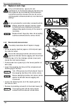
Страница 32: ...r 4 2 apply Lift the sweeping machine approx 200 mm and open the collector vessel Secure the sweeping machine and carrier vehicle against unintended restart sagging and movement Close the tap 1 for the drainage cylinder must point toward the rear castor wheels Put the raster lever system 2 in the lowest position on both sides Lower the sweeping machine until the complete brush shaft is lying on th...

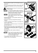
Страница 33: ... hydraulic motor 8 out of the drum shaft 9 Pull the drum shaft 9 out beneath the sweeping machine Lower the sweeping machine frame 10 and place it on the rear support rollers Remove the four countersink screws 11 and unmount the holding plate 12 Replace worn out brush rings For the quantity of brush rings see the list of spare parts Brush set Snowline Sunline Beeline 50 Sunlind and 50 corrugated w...

Страница 34: ... start up and movement Tilt the side broom upward move from pos A to pos B and click the lever 4 into place 5 see Chapter 3 2 3 Screw off the three hexagonal nuts 1 Take the plate broom s net weight into account Remove old plate brooms 2 and drill a hole through the new plate broom to suit the lange 3 Mount plate broom using new self securing nuts Swing the side broom into operating position and r...

Страница 35: ...sel is necessary Take into account the net weight of the impact rail and the Vulkollan rail Loosen the fastening nuts 3 and screws 4 along the entire length of the Vulkollan rail 1 Remove the impact rail 2 and the old Vulkollan rail 1 Replace the Vulkollan rail 1 The installation is carried out in the opposite order 4 5 Water spraying device The water ilter is located at the suction hose 4 in the ...

Страница 36: ...Service and maintenance 36 N O T E 4 6 Lubrication plan Grease the bearings weekly Use grease according to DIN 51502 e g Gresalit 2 by Westfalen Grease weekly ...

Страница 37: ...d Hydraulic connections not correct Hydraulic cylinder defective Turn the 2 way tap Check connections Ask a qualiied workshop 3 Water spraying device does not function Water tank empty Fuse in the cabinet defective Water ilter clogged Nozzles clogged Top up water Replace the fuse Clean water ilter Clean nozzles 4 Side broom does not move Intake hose closed Hydraulic connections not correct Flow co...

Страница 38: ...3 1 14 1 15 1 13 1 14 1 15 1 16 1 17 1 9 1 10 1 11 1 12 2 2 1 2 2 2 3 2 4 2 5 2 6 2 7 2 15 2 8 2 9 2 13 2 10 2 11 2 12 2 14 2 15 2 16 2 17 2 21 2 18 2 19 2 20 3 3 1 3 2 3 3 3 4 3 5 3 6 3 7 3 8 3 9 3 11 3 10 3 13 3 14 3 15 3 16 3 17 4 4 1 4 4 1 4 2 4 2 4 3 4 4 4 5 4 5 4 6 4 7 4 8 4 9 4 10 4 10 4 12 4 13 4 14 5 5 1 5 2 5 3 5 4 5 4 Sammelbehälter Seitenkehrbesen Seitenverstellung Walzenwelle Side bro...

Страница 39: ... itting with sealing cone 1 2 17 40003071 T reduction 1 2 18 40001471 Hydraulic pipe 1 2 19 40001400 Lock nut 2 2 20 40001402 Progressive stop ring 2 2 21 40001407 Straight intermediate itting with sealing cone 1 3 40000072 Hydraulic motor 1 3 1 40002188 Straight screw in sleeve 2 3 2 40003062 One way restrictor adjustable 1 3 3 40001271 Straight screw in sleeve 2 3 4 40003072 Straight intermediat...

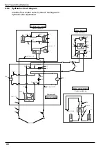
Страница 40: ... 4 2 4 5 4 5 4 6 4 7 4 8 4 9 4 12 4 13 4 14 5 5 1 5 2 5 3 5 4 5 4 Sammelbehälter Seitenkehrbesen Seitenverstellung Walzenwelle 1 1 1 1 2 1 3 1 4 1 5 1 6 1 10 2 2 1 2 2 2 3 2 4 2 5 2 6 2 7 2 8 3 3 1 3 14 4 4 1 4 4 1 4 3 4 4 4 10 4 10 4 8 2 Hydraulic circuit diagram Includes low control valve hydraulic drainage and hydraulic side adjustment Side broom Side adjustment Drum shaft Collector vessel ...

Страница 41: ...188 Straight screw in sleeve 2 3 2 40003062 One way restrictor adjustable 1 3 3 40001271 Straight screw in sleeve 2 3 4 40003072 Straight intermediate itting with sealing cone 1 3 5 40003063 T itting 1 3 6 40003064 T itting with sealing cone 1 3 7 40001584 Hydraulic pipe 2 3 8 40001585 Lock nut 6 3 9 40001586 Progressive stop ring 6 3 10 40001261 Elbow itting with sealing cone 1 3 11 40003073 Elbo...

Страница 42: ..._________________________________ __________________________________________________________________________ __________________________________________________________________________ __________________________________________________________________________ __________________________________________________________________________ __________________________________________________________________...

Страница 43: ..._________________________________ __________________________________________________________________________ __________________________________________________________________________ __________________________________________________________________________ __________________________________________________________________________ __________________________________________________________________...

Страница 44: ...____________________________________________________________ __________________________________________________________________________ __________________________________________________________________________ __________________________________________________________________________ __________________________________________________________________________ _______________________________________...

Отзывы: