Tubeline Boss I Скачать руководство пользователя страница 12

12

PROCESSOR MAINTENANCE

Regular maintenance is the key to long equipment life and safe operation. It is very 

important that these maintenance functions be performed as described below.

SAFETY FIRST!! READ AND UNDERSTAND THE SAFETY INSTRUCTIONS 

(pages 3-6 of this manual)

BEFORE BEGINNING ANY PROCESSOR MANTENANCE OPERATION

IMPORTANT

The flail tube on this machine is a fully balanced assembly. If for any reason the flails must be removed, 

they must be returned

to the 

same position

they were taken from. If this is not done a balance problem 

will result in causing machine vibration. Number flails and inserts and their positions before you do any 
work.

BEFORE FIRST USE

Inspect the attachment for shipping damage. If damage does exist, do not operate until the damaged parts 
have been replaced or repaired.

BEFORE EACH USE

Check for loose or badly worn parts.

Conveyor chain should be adjusted to allow chain slack 1” (2.54 cm) to 1½” (3.8 cm).
Make sure that all hydraulic fittings are tightened and that there are no leaks in any fittings or hoses.
Inspect rotor and all rotating parts for twine or wire build-up.
Check for cylinder wear and broken flails and flail bracket wear. Replace with new “

Boss

” flails to keep 

machine in balance.
Make sure that all safety signs are in place, are clean and are legible.

SEE THE SAFETY SIGN SECTION 

(page 6)

AFTER EVERY 10 HOURS OF OPERATION

Grease all roller bearings.  (

refer to diagram on page 10)

Inspect and tighten Allen screws on bearing.

PROCESSOR SERVICE

SAFETY FIRST!! READ AND UNDERSTAND THE SAFETY INSTRUCTIONS 

(

pages 3-6 of this manual)

BEFORE BEGINNING ANY PROCESSOR SERVICE.

WARNING

Hydraulic fluid under pressure can penetrate skin, resulting in serious injury or death.

Always relieve hydraulic pressure before disconnecting lines.

Shut off engine, set parking brake and relieve hydraulic pressure before connecting or 

disconnecting hydraulic lines. Refer to your power unit’s manual for instruction on how to 
relieve hydraulic pressure in lines.
Before applying pressure to the system, be sure that all connections are tight and be sure there 
are no damaged hoses, lines or fittings.
Wear safety glasses and use metal or wood when searching for leaks. Do not use your hands.

WARNING

Before servicing the loader, remove the attachment
and make certain the lift arms are lowered to their lowest position 

or that the arms are supported by the mechanical lock up devices (if the machine is so equipped).

Steam-clean the power unit before any installation is made to the hydraulic system. 
Remove any attachment from the power unit and position on a level surface. 

Содержание Boss I

Страница 1: ...Operator s Manual Tube Line Bale Processor Boss I ...

Страница 2: ......

Страница 3: ...d Safety Information 3 6 Definitions of Safety Terms and Symbols Accident Prevention 3 Safety Instructions 4 5 Safety Signs 6 Power Unit Specifications 7 Installation Instructions 7 Hydraulic Instructions 7 Operation 8 Maintenance 9 Service 9 Grease Points 10 Deck Assembly 11 Top Beater Assembly 12 Bottom Beater Assembly 13 Ram Assembly 14 Hydraulic Schematic 15 Warranty Policy 16 ...

Страница 4: ...is product is being handled or used Provide this manual to any new owners and or operators GENERAL INFORMATION The purpose of this manual is to assist you in safely assembling mounting operating and maintaining your Boss I Read this manual carefully to obtain valuable information and instructions that will help you achieve safe and dependable service The illustrations and data used in this manual ...

Страница 5: ...ident prevention program can be successful without the wholehearted cooperation of the person who is directly responsible for the operation of the equipment If accidents are to be prevented and accidents can be prevented that prevention will come from equipment operators who accept their complete responsibility and anticipate the results of their actions The designer the manufacturer and the safet...

Страница 6: ... your tools are in good condition for performing the desired function When using tools wear the protective equipment specified by the tool manufacturer i e hardhat safety glasses work gloves protective shoes etc WHEN YOUR POWER UNIT IS USED DURING ANY TYPE OF ASSEMBLY OPERATION MAINTENANCE OR OTHER WORK ON OR NEAR THIS PRODUCT Before leaving the operator s station or before beginning any type of w...

Страница 7: ...ans that all devices function properly and that there are no fluid leaks WHEN MOUNTING THIS PRODUCT TO YOUR POWER UNIT Refer to the operator s manuals of your power unit your loader and your quick attach for special or detailed mounting instructions This product should fit onto the quick attach or loader arms of your power unit the same as the original products that were designed by your loader qu...

Страница 8: ...from the safety sign exposing the adhesive surface Apply the safety sign to the position shown in the diagram above and smooth out any bubbles INSTRUCTIONS Keep all safety signs clean and legible Replace all missing illegible or damaged safety signs Replacement parts for parts with safety signs attached must also have safety signs attached Safety signs are available free of charge from your dealer...

Страница 9: ...9 ...

Страница 10: ...arms and cycle the tilt cylinders to check clearances and to verify that all mounting procedures have been successfully completed SAFETY FIRST READ AND UNDERSTAND THE SAFETY INSTRUCTIONS pages 3 6 of this manual BEFORE BEGINNING ANY PROCESSOR MOUNTING Processor Hydraulic Connection SAFETY FIRST READ AND UNDERSTAND THE SAFETY INSTRUCTIONS pages 3 6 of this manual BEFORE BEGINNING ANY HYDRAULIC CONN...

Страница 11: ... to your power unit s operator s manual for safe operating limit and use of counterweights To Load Load one bale at a time If bales are frozen put frozen side down to the table for better operation Center the bale on the forks before loading on to the table Slide forks lightly on the ground when loading bales Store bales on level ground and on a clean surface free from rocks and other foreign obje...

Страница 12: ... flails to keep machine in balance Make sure that all safety signs are in place are clean and are legible SEE THE SAFETY SIGN SECTION page 6 AFTER EVERY 10 HOURS OF OPERATION Grease all roller bearings refer to diagram on page 10 Inspect and tighten Allen screws on bearing PROCESSOR SERVICE SAFETY FIRST READ AND UNDERSTAND THE SAFETY INSTRUCTIONS pages 3 6 of this manual BEFORE BEGINNING ANY PROCE...

Страница 13: ...13 ...

Страница 14: ...14 ...

Страница 15: ...15 ...

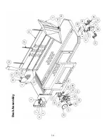
Страница 16: ...16 Deck Assembly ...

Страница 17: ...x Bolt 13 2 HB 5 8 X 2 25 Hex Bolt 14 3 HN 5 8 Hex Nut 15 9 HB 3 8 X 1 Hex Bolt 16 1 B1 079 Adjuster Bracket 17 5 LW 3 8 Lock Washer 18 1 HN 3 8 Hex Nut 19 1 BS200141A Sprocket Assembly 20 1 BS200138A Chain Drive Sprocket 21 1 B1 082 Chain Tightener 22 1 SPR60B30F IH Sprocket 23 4 BS199398A Drive Sprocket Bearing 24 8 LW 5 8 Lock Washer 25 2 FW 5 8 Flat Washer 26 2 LN 5 8 Lock Nut 27 3 LA MFE43 Ti...

Страница 18: ...18 Top Beater Assembly ...

Страница 19: ...Lock Washer 9 15 HB 3 8 X 1 Hex Bolt 10 13 LN 3 8 Lock Nut 11 12 LN 5 16 Lock Nut 12 8 HB 3 8 X 1 5 Hex Bolt 13 6 FW 3 8 Flat Washer 14 4 HN 3 8 Hex Nut 15 1 B1 077 Rubber Deflector 16 1 B1 075 Rubber Deflector Mount 17 3 HIN 3 5 X 3 5 Hinge 18 8 CB 1 4 x 1 Round Head Bolt 19 14 HN 1 4 Hex Nut 20 14 LW 1 4 Lock Washer 21 6 CB 1 4 X 75 Round Head Bolt 22 1 25576 Top Beater Shield 23 1 VAL 1008 Moto...

Страница 20: ...20 Bottom Beater Assembly ...

Страница 21: ...K 1 4TBW SK Taper Lock Bushing 1 1 4 Bore 3 1 B1 032 1 Main Beater Shaft 4 1 B1 031 Flail Mount Lug 5 1 SAW200059 Flail Bushing 6 1 SAW200060 Flail 7 2 Obtain Locally HN 5 8 Hex Nut 8 2 Obtain Locally HB 5 8 x 4 Hex Bolt Square Key x 3 Bottom Beater Assembly ...

Страница 22: ...22 Hydraulic Layout 1 2 3 4 5 6 7 8 9 ...

Страница 23: ...6 Ram Motor to Block Small 3 1 28207 Top Motor to Block Large 4 1 28208 Top Motor to Block Small 5 1 28209 Flail Motor to Block Large 6 1 28210 Flail Motor to Block Small 7 1 28242 Connector to Block Lower 8 1 28243 Connector to Block Upper 9 1 28036 Block Hydraulic Layout ...

Страница 24: ...24 Optional 3 rd Beater Kit ...

Страница 25: ... Hole Flange 5 19 Obtain Locally LN 5 8 Lock Nut 6 17 Obtain Locally HB 5 16 x 3 4 Hex Bolt 7 6 Obtain Locally HB 7 16 x 1 Hex Bolt 8 1 25786 Middle Guard 9 6 Obtain Locally FW 7 16 Flat Washer 10 15 Obtain Locally FW 5 16 Flat Washer 11 2 SPR50B16F 1 Sprocket 12 1 27005 Top Beater Idler Shaft 13 4 Obtain Locally HB 5 16 x 1 Hex Bolt 14 1 27209 Top Beater ...

Страница 26: ...26 ...

Страница 27: ...27 ...

Страница 28: ...28 ...

Отзывы: