background image

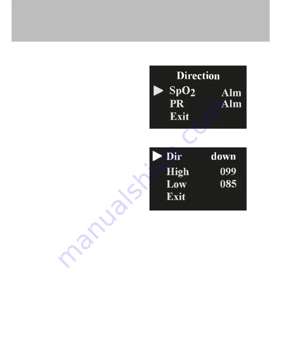
Press the button (1sec) to enter the alarm direction setting interface as 

shown in Figure 9:

Easi-Pulse

TM

On the alarm direction setting 

interface, Click the power button to 

select “SpO2 Alm”or “PR Alm”, then 

Press the button (1 sec) to enter the 

SpO2 or PR direction setting interface 

as shown in Figure 10:

Click the power button to select “Dir”, 

then Press the button to choose Up 

or Down (this will be the direction the 

value of the high-low limits of SpO2 

and pulse rate will be adjusted)

To raise the SpO2 and pulse rate limit, 

choose “Dir” as ‘Up’, then Click the 

power button to select high limit 

(High) or low limit (Low), Press the 

power button and hold to adjust the 

selected limit to the desired higher value and release the power button once 

the higher limit has been reached.

To lower the SpO2 and pulse rate limit, choose “Dir” as ‘Down’, then Click 

the power button to select high limit (High) or low limit (Low). Press the 

power button and hold to adjust the selected limit to the desired lower 

value and release the power button once the lower limit has been reached.

b. Pulse sound indication setting

On the alarm setting interface as shown in Figure 8, Click the power button 

to select “Psound”, then Press the power button to choose to have the Pulse 

Sound (heart beat) alarm “on” or “off”.

Figure 9

Figure 10

13

Содержание Easi-Pulse

Страница 1: ...tts group co uk for the latest product information Email feedback tts group co uk for technical support TTS Group Ltd Park Lane Business Park Kirkby in Ashfield Nottinghamshire NG17 9GU UK Freephone...

Страница 2: ...measures the pulse oxygen saturation and pulse rate Easi PulseTM www tts shopping com USER GUIDE...

Страница 3: ...e user and equipment Refer to the respective chapters for details Please read the User Manual carefully before using this product The User Manual which describes the operating procedures should be fol...

Страница 4: ...r than 2 hours n The device cannot be clipped on the edema or tender tissue n Do not attempt to look directly at the infra red light emitter n Remove all cosmetics from the finger nail before use n Pl...

Страница 5: ...ormance 4 2 Main Parameters 5 Installation 5 1 View of the front panel 5 2 Battery installation 5 3 Accessories 6 Operating Guide 6 1 Application method 6 2 Operation 6 3 Clinical restrictions 7 Maint...

Страница 6: ...calibrated before leaving factory 1 2 Warning n Explosive hazard DO NOT use the oximeter in an environment with inflammable gas such as some ignitable anesthetic agents n Ensure that the environment i...

Страница 7: ...value n If some abnormal symbols appear on the screen during use pull out the finger and reinsert to restore normal use n This device has an alarm users can check on this function according to chapte...

Страница 8: ...hPa 1060hPa 3 Principle Principle of the Oximeter is as follows using Lambert Beer Law and according to Spectrum Absorption Characteristics of Reductive Hemoglobin Hb and Oxyhemoglobin HbO2 in glow ne...

Страница 9: ...n be changed G A pulse rate sound indication H Alarm function I With SpO2 value and pulse rate data storage the stored data can be uploaded to computers J Data can be transmitted to computers 4 2 Main...

Страница 10: ...esistance to surrounding light The deviation between the value measured in the condition of man made light or indoor natural light and that of darkroom is less than 1 F Power supply requirement 2 6 V...

Страница 11: ...igure 4 Put finger in position Figure 3 A a Insert the two batteries ensuring the correct polarity and then replace the cover b Open the clip as shown in Figure 4 c Insert the finger into the foam rub...

Страница 12: ...er two icons will appear on the desktop after installation SpO2 is a program for receiving real time data which is shown as Figure 5 the icon of SpO2 Review is a program for receiving stored data whic...

Страница 13: ...u interface click the power button to select Alarm Press the power button 1sec to enter the alarm setting interface as shown in Figure 8 Press and hold the power button 1 second to enter the Settings...

Страница 14: ...ick the power button to select high limit High or low limit Low Press the power button and hold to adjust the selected limit to the desired higher value and release the power button once the higher li...

Страница 15: ...store the data or not choose on to allow storing choose off to prevent storing b If the data storage is turned on the main user interface will show a flashing yellow dot c Whilst recording the screen...

Страница 16: ...adhesive E Excessive ambient light may affect the measuring result F Strenuous action of the subject or extreme electrosurgical interference may also affect the accuracy G Please clean and disinfect t...

Страница 17: ...ot placed inside deep enough 2 The finger is shaking or the patient is moving 1 The battery is flat 2 The battery is installed incorrectly 3 The device is faulty 1 This device is set to automatically...

Страница 18: ...button function button Type BF Serial number 1 the finger clip falls off no finger inserted 2 Probe error 3 Signal inadequacy indicator battery positive battery negative USB Ingress of liquids rank W...

Страница 19: ...resolution is 1 70 100 2 Below 70 unspecified Calculate the Average value in every 4 measure value The deviation between average value and true value does not exceed 1 30bpm 250bpm the resolution is 1...

Страница 20: ...f the user of the CMS50D should assure that it is used in such and environment Emission test RF emissions CISPR 11 RF emission CISPR 11 Compliance Group 1 Class B Electromagnetic environment guidance...

Страница 21: ...he relative humidity should be at least 30 Mains power quality should be that of a typical commercial or hospital environment Guidance and manufacturer s declaration electromagnetic immunity for all E...

Страница 22: ...ion applicable to the frequency of the transmitter Recommended separation distance Where P is the maximum output power rating of the transmitter in watts W according to the transmitter manufacturer an...

Страница 23: ...adcast and TV broadcast cannot be predicted theoretically with accuracy To assess the electromagnetic environment due to fixed RF transmitters an electromagnetic site survey should be considered If th...

Страница 24: ...0 MHz to 800 MHz 800 MHz to 2 5 GHz 0 01 0 1 1 10 100 Rated maximum output power of transmitter W Separation distance according to frequency of transmitter m 0 23 0 74 2 33 7 38 23 33 For transmitters...

Отзывы: