TTI Buddy BX4 Скачать руководство пользователя страница 41

6.9 Use PTZ 

6.9.1 PTZ Control 

B u d d y   B X 4  


41 -

1) Connect the RS485 of DVR system to PTZ communication port.
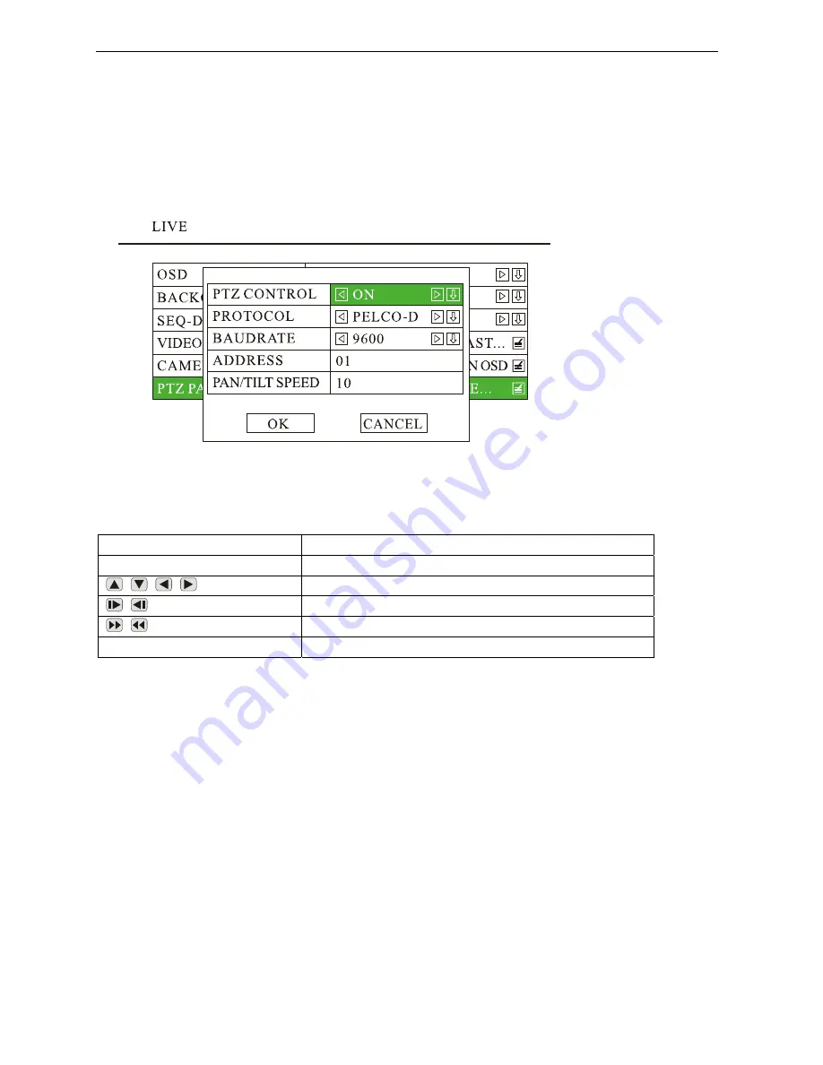
2) Press

<MENU>

 to enter DVR system menu, choose “LIVE” and press 

<MENU>

 to enter its sub-menu,

go to “PTZ PARAMETER” and press 

<MENU>

 to enter, set the “PTZ CONTROL” as “ON”, set other

parameter if needed. Press 

<OK>

 to save and exit.

3) Use the remote to control PTZ: Press 

<ESC>

 to escape from the DVR system menu, press <OK> to

get

4) “PTZ CONTROL”. Key buttons for PTZ control:

Key Buttons on Remote 

Function 

VIDEO 

Select camera channel (CH:01, CH:02, CH:03, CH:04 

/

/

/

Move camera direction 

/

Zoom - / Zoom + 
Focus + / Focus - 

/

PAUSE/OSD 

Iris+ / Iris- 

6.9.2 Rename the camera 

1) Press 

<MENU>

 to enter the DVR system menu, choose “LIVE” to enter its sub-menu, go to “OSD”

and set it as “ON”,

2) Press 

<MENU>

 to enter the DVR system menu, choose “LIVE” to enter its sub-menu, go to “CAMERA

TITLE” and press 

<MENU>

  to  enter,  rename  each  camera  by  press 

<MENU>

 to get the “TEXT

INPUT” dialog box:

Содержание Buddy BX4

Страница 1: ...our SD Video Recorder This manual is applicable for 1ch 2ch and 4ch SD Video Recorder Please read this User s Manual carefully to ensure that you can use the device correctly and safely The contents o...

Страница 2: ...cause Important notice 1 Please read over all cautions 2 Please keep this manual for reference in the future 3 Please notice all warning information 4 Please strictly follow the instructions in this...

Страница 3: ...16 5 BASIC OPERATION AND MENU SYSTEM 17 5 1 SD CARD FORMATTING 17 5 2 CHOOSE RECORDING MODE 18 5 3 FILE LENGTH 19 5 4 RECORDING QUALITY 19 5 5 START RECORDING 21 5 6 PLAYBACK OPTION 22 5 6 1 Playback...

Страница 4: ...turn on off the DVR system 39 6 8 2 Turn On Off DVR System Automatically 40 6 9 USE PTZ 41 6 9 1 PTZ Control 41 6 9 2 Rename the camera 41 6 9 3 Video Adjustment 42 6 10 GPS SETTING OPTION 43 6 11 EV...

Страница 5: ...at may cause undesired operation Product Description The SDVR unit consists of the following major components Standard Components and Features Extruded aluminum case the case is anodized in cobalt blu...

Страница 6: ...battery voltage after Ignition off and auto into sleep mode when voltage is bellow specified level Recording mode Continuous record Support schedule recording Support alarm recording Support motion d...

Страница 7: ...VR is on running Blinking with RUN by turns Blinking with PWR by turns Ignition is not enabled and SDVR is OFF Blinking together with RUN Blinking together with PWR Ignition sense is not enabled SDVR...

Страница 8: ...audio input 1 video input 1 and power output for camera 3 AV input 4 including audio input 1 video input 1 and power output for camera 4 AV output including audio output video output and power output...

Страница 9: ...g different value in the submenu You can also use MENU as OK 2 Press UP DOWN LEFT RIGHT button to move between the different menu item 3 Press OK to save and exit the current menu Press ESC to cancel...

Страница 10: ...oof case in the right place inside the vehicle 2 Put the DVR system inside the bottom cover and load a SD Card NOTE The lock jumper of SD Card should be in OFF position Kingston Class 4 or above Trans...

Страница 11: ...DVR may be damaged if the voltage comes too high And the DVR may not work if the voltage comes too low 3 Power of the DVR should be supplied by the car battery 4 Power consumption of the DVR can be 6...

Страница 12: ...Camera Connection Two different kinds of Audio Video Cables for option 1 4 pin threaded cable with male connector for each camera Pin 1 12V power Pin 2 GND Pin 3 Audio Input Pin 4 Video Input Buddy BX...

Страница 13: ...stem will provide stable 12V DC power to each camera and record video and audio if the camera is with microphone built in This type of connection cable is highly recommended It saves both installation...

Страница 14: ...3 4 Sensor Harness Connection GPS Connection Option PIN Description 3 RXD2 Data receive 5 GND Ground 9 5V DC Power output Buddy BX4 14...

Страница 15: ...3 5 Event Button and Cable Connection Option Buddy BX4 15...

Страница 16: ...4 Main System Overview Buddy BX4 16...

Страница 17: ...er which can be downloaded from internet free of charge is recommended to be used for fast formatting and batch processing 2 If the SD Card is never formatted or the file system is corrupted you may h...

Страница 18: ...cording modes for option Composite Mode and Separate Mode The defaulted recording mode is Separate Mode You can change to Composite Mode by steps given as below if needed a Press MENU by remote b Choo...

Страница 19: ...and 60mins The defaulted file length is 5 minutes The maximum file length is 60 minutes 5 4 Recording Quality Press MENU to enter the DVR system menu choose RECORD and enter its sub menu go to RECORD...

Страница 20: ...PAL 480 384 NTSC 480 320 350K 210K 64K 198M hour NORMAL D1 PAL 720 576 NTSC 720 480 1000K 600K 64K 324M hour GOOD D1 PAL 720 576 NTSC 720 480 1200K 720K 64K 432M hour HIGH D1 PAL 720 576 NTSC 720 480...

Страница 21: ...t corner of each camera channel In Separate Mode by default the DVR system will record all channels If you want to record a specific channel s use or number key 1 2 3 4 to select the camera channel s...

Страница 22: ...k the latest file of first camera channel ch 01 Use or number key indicated by a green triangle on the top right corner of monitor ou press 1 2 3 4 to select a specific camera channel and press PLAY t...

Страница 23: ...ll be listed ll be listed by order of the date and hour To take 2011 04 27_14 P a for option The directories wi for an example it means this directory contains all files recorded from 14 00 00 to 14 5...

Страница 24: ...d on the CD onto your PC em NU to enter the record directories Enter one directory and select a specific file needed to be copied press OK or MENU to b Remove the SD card from DVR system and read on a...

Страница 25: ...nsor Alarm 3 SENSOR4 Violet Speed Sensor P U ote to e m menu choose ALARM and press MENU to enter i G ARM AC s MENU to enter ress MEN by rem nter the DVR syste ts sub menu o to AL TION and pres Taking...

Страница 26: ...LEVEL HIGH LOW High means Alarm input voltage higher than 5V and Low means lower than 3V TOGGLE It will toggle to the camera you set in full screen automatically when sensor alarm is triggered There...

Страница 27: ...tor by using and NOTE Please press MENU by remote to confirm after choosing each zone if you need select more than one zone 5 9 2 Set Motion Detection Action Press MENU to enter the DVR system menu ch...

Страница 28: ...r to sensitive level 1 9 levels for option 1 refers to lowest sensitive level and 9 refers to highest 6 0 Video Lost Alarm he buzzer can be set as ON to trigger the beeper when any video lost Press ME...

Страница 29: ...CORD SETTINGS and press MENU to enter The defaulted REC MODE is AUTO change it to MANUAL by press MENU press OK to save and exit Go to RECORD SCHEDULE and set the recording time 6 2 Video System Setti...

Страница 30: ...the DATE FORM 6 3 2 Set The Time Zone Press MENU to enter the DVR system menu choose SYSTEM and press MENU to enter its sub menu choose TIME ZONE and press MENU to enter go to TIME ZONE and select th...

Страница 31: ...USER CONFIG RESET and press MENU to reset 3 Factory Reset The user can press FACTORY RESET to reset to the factory defaulted settings After this is pressed the system will restart automatically 4 Conf...

Страница 32: ...EW PASSWORD and set the password Input the same password in both rows of New Pass and Pass Confirm press OK or MENU to save and exit 6 6 Network Setting The system supports both Static IP and Dynamic...

Страница 33: ...ose IP ADDRESS SUBNET GATEWAY and DNS SERVER to set each option After setting please press MENU or OK to save and exit 2 If it is dynamic IP the system will configure the IP address automatically 3 HO...

Страница 34: ...NSE ID and LINE Press MENU to enter DVR system menu choose MOTOR and press MENU to enter its sub menu Set the LICENSE ID and LINE press OK to save and exit The information will be displayed at the top...

Страница 35: ...y Sensor 2 6 SPEED Violet Speed sensor 7 RXD1 Vacant RXD COM1 GPS 8 RXD2 Blue RXD COM2 Pin 3 9 485B Vacant RX485 B PTZ 10 GND Black Ground Pin 5 11 SNR3 Grey Sensor 3 12 SNR1 Grey Sensor 1 GPS connect...

Страница 36: ...ve and exit 3 he spe ll be disp n the lef of the monitor I eed the speed to be MPH other han K lease s le in ES UNIT NOTE If no GPS device is connected to the DVR system speed on monitor will stay as...

Страница 37: ...ect Speed sensor input wire to the SIG output wire directly 3 If the speedometer does NOT have a signal output wire please connect to the output of speed sensor This could also be input of the speedom...

Страница 38: ...car runs for one kilometer Then set the number to Pulse No 6 While in a real application it s not easy to pulse number by the calculation on the paper In this case you can choose the menu item 10 Veh...

Страница 39: ...record for the prescribed number of and DVR system shut off right after the ignition switch if in the OFF position seconds When the off delay expires the camera and DVR system shut off 3 Set OFF DELA...

Страница 40: ...2V or 24V of car battery 2 Press MENU to enter DVR system menu choose POWER and press MENU to enter its sub menu a Go to POWER ON and set the time you would like the DVR system to be turned on b Go to...

Страница 41: ...SC to escape from the DVR system menu press OK to get 4 PTZ CONTROL Key buttons for PTZ control Key Buttons on Remote Function VIDEO Select camera channel CH 01 CH 02 CH 03 CH 04 Move camera direction...

Страница 42: ...djust the brightness contrast hue and saturation 2 ress OK to save and exit or ESC to discard the change If you want to resume to the tings just go to D d press MENU or OK to confirm ation of PTZ cont...

Страница 43: ...he time d BAUDRATE refers to GPS communication baudrate The defaulted baudrate is 4800 2400 9600 19200 38400 57600 115200 for options 6 11 Event Button Cable Setting Option b GPS BURNIN can shown on t...

Страница 44: ...se Separate Mode for recording press MENU to enter the DVR system menu choose ALARM and press MENU to enter its sub menu go to ALARM ACTION to set the camera channel There are a total of 16 modes OFF...

Страница 45: ...the DVR unit b Press the Event button the LED will flash in red and you will hear buzzer if you set the BEEP as ON it means alarm recording is triggered c The alarm recording is recorded in the log f...

Страница 46: ...m press MENU by remote to enter the DVR system menu 3 Choose SYSTEM and press MENU to enter its sub menu 4 Choose SYSTEM INFO go to APP UPDATE and press MENU to get ready for system update 6 12 Firmwa...

Страница 47: ...pdate file yo to select the right directory if there is more than one found Press MENU to continue NOTE Do not turn off the power while updating 7 Upgrade Success will be shown up to remind you when u...

Страница 48: ...n 7 or Vista please choose 1 Debug the Wi Fi module on PC a Connect Wi Fi module to a PC s USB and LAN ports If the operation system is WinXP please choose then go with NEXT to finish the installation...

Страница 49: ...NK_TENDA to connect to press Next input the ascii code of your password in hex format You can look up the ascii code of your password in the ascii table Appendix A For an example if your password is h...

Страница 50: ...supplier s reviewing software into your PC You will get three icons of ViewPro AVPlayer and Record Calculator on your PC desktop ViewPro is used for live view file download set DVR remotely etc AVPla...

Страница 51: ...om crimp side Mark Color Description PWR RED of power supply you can connect to Battery ACC YELLOW Ignition signal Connect this wire to of power supply if you don t use ignition to control the power G...

Страница 52: ...in White Audio input 12V DC Connector in Black Power output for camera 12 VDC Maximum current 1A GND Ground 2 Video Audio Output Cable de Viewed from crimp si Mark Color Description VO BNC Connector...

Страница 53: ...S485 A 4 5 0V Red 5 VDC Pin 9 5 SNR2 Grey Sensor 2 6 SPEED Violet Speed sensor 7 RXD1 Vacant OM1 GPS RXD C 8 RXD2 Blue RXD COM2 Pin 3 9 485B Vacant RX485 B PTZ 10 GND Black Ground Pin 5 11 SNR3 Grey S...

Страница 54: ...G OMPRE 711 STORAGE AGE SD card ex vice memory stick or hard drive STOR ternal USB de FILE FORMAT AVI INTERFAC NSORS 1 ignition ensor 3 sensors for brake return etc E SE speed sensor 1 s COM POR 2 1 R...

Страница 55: ...four channe 5 AV output cable 1 pc 6 Signal cables 1 pc 7 Powe 1 r cable pc 8 Remote Controller 1 pc 9 Fuse 1 box pc 10 1 5A fuse 2 pcs 11 Screw 4 s pcs 12 User s Manual 1 pc Options Item Des Quantity...

Страница 56: ...s ground is not a reference ground nymore Please see the Appendix in the back including the potential analysis diagram against cars with negative switch control 5 Q Respectively what s the voltage ref...

Страница 57: ...card DVR can directly support two kinds of media 1 SD card With good writing speed and quality there are Kingston Transcent etc brands the market It is more reliable for its conventional speed values...

Страница 58: ...ht this indicator light will shine timely when DVR recording or playing The fifth yellow indicator light on the panel is SD card recording indicator light if this light on it means DVR is recording th...

Страница 59: ...Recording Mode that is to composite multiple front end camera images into a high definition image such as 1280x1024 and coder at one point in time there has been only 1 high definition AVI files recor...

Страница 60: ...First please make sure that if the sensitivity settings of the motion detection are correct sensitivity i is the lowest sensitivity Second make sure that if your camera system PAL system or NTSC s e s...

Отзывы: