Copyright © 2020 TTAAll Rights Reserved.
G200 Manual
8
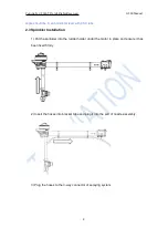
3) Mount the arm and match the 6mm inner hole of arm joint with body’s joint 6mm
inner hole.
4) Install the M5*57.2 plug screw from the hexagon side of the 6mm hole on body’s
arm joint, and tighten the M5 nut on the other side to lock the plug screw as figure 4
5) Install the rest 5 arms as above.
Attention:
1) The difference between CCW arm and CW arm is different rotation direction of the
propellers which produce lift force. There is a mark arrow on every motor holder to help
differentiate. CCW arrow means CCW arm, you need to install the CCW
propeller,otherwise it will be CW arm which you need to install the CW propeller.
2)The camera points to the orientation of aircraft head.
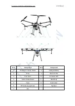
3) Attention: CCW M1 arm with Red LED, CW M2 arm with Red LED, CCW M3 arm
with Green LED and nozzle, CW M4 arm with Green LED, CCW M5 arm with Green LED,
CW M6 arm with Green LED and nozzle.
4) Arm could only fold down instead of up during the arm installation. The max lift
Figure 3
Figure 4


