


Introduction
1 - 8 Top View
1
PC Camera
If you have purchased the
optional
PC Camera, make sure to install the soft-
ware application (see
“PC Camera” on page 7 - 10
).
LCD Panel
The computer comes with a 14.1"
OR
a 15.0" TFT (Liquid Crystal Display)
screen, depending upon the configuration purchased. See
“LCD Options” on
page A - 2
for details.
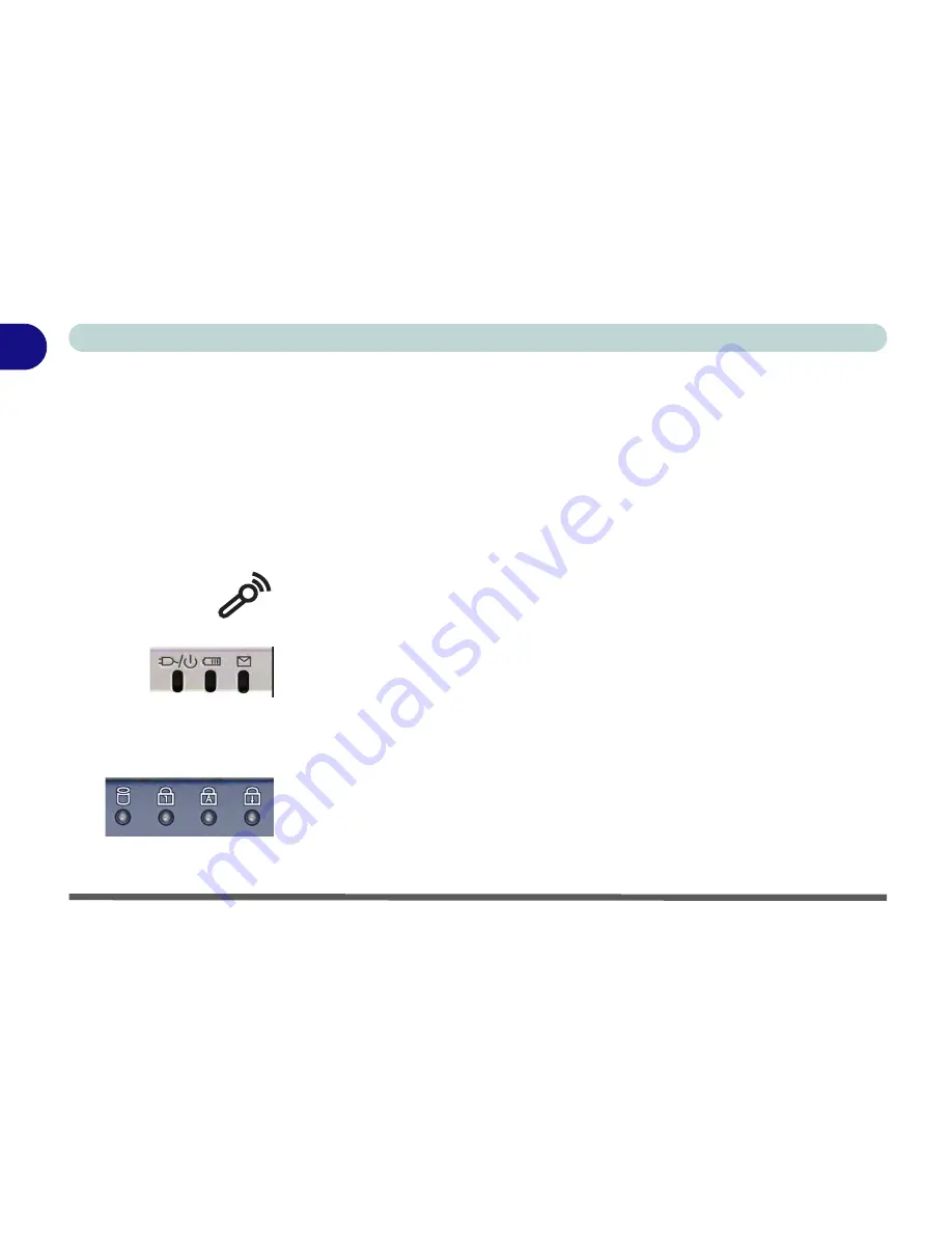
Microphone
Record on your notebook computer with the built-in microphone.
LED Power & Communication Indicators
These indicators display the system power status, and battery status of the
computer. The third indicator may be configured to give a visual confirmation
when e-mail is received in the default e-mail program (see
“LED Power &
Communication Indicators” on page 2 - 6
).
LED Status Indicators
These display the system’s operational status. Refer to
“LED Status Indica-
tors” on page 2 - 5
for more information on what the lights mean.
Содержание Slider D400S
Страница 1: ......
Страница 2: ......
Страница 42: ...Introduction 1 22 1...
Страница 110: ...Drivers Utilities 4 16 4...
Страница 182: ...A 6 A...


