


disturbance. Shielding has no effect on this problem; the only solution is to keep strobe light wiring as far away as possible
from any electronics which can be affected by pulsating magnetic fields.
RFI/EMI considerations
The autopilot programmer is shielded and does not generate any appreciable level of electromagnetic interference. Moreover,
the servo lines (except for power and ground) are low-current and cannot contribute to RF interference. The servo power and
ground lines do have switching currents through them, but so long as there are no parallel runs of servo power and ground lines
with such things as poorly-shielded antenna lines or strobe light power lines, there is no need to shield the servo harnesses.
The autopilot itself has been internally protected from RF interference and has been tested under fairly extreme conditions,
such as close proximity to transmitting antennas. However, it is always good practice to insure that such antennas are properly
shielded and not routed directly over or under sensitive panel-mounted electronic equipment. Most problems in this area are the
result of improper RF shielding on transmitting antennas, microphone cables, and the like. The most sensitive input to the
autopilot is the Control Wheel Switch input. This line should not be routed in parallel with transmitting antennas or other
sources of known RF interference. If necessary, it can be shielded with the shield connection to pin 8 of the autopilot
connector.
Electrical Wiring
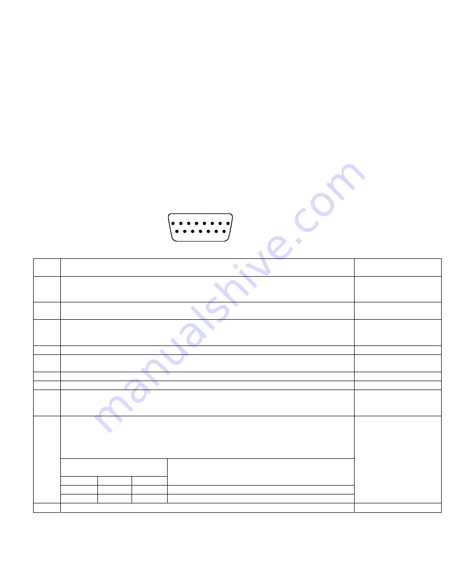
The table below provides a brief explanation of each pin function on the main 15-pin connector P101.
1
9
10 11 12 13 14 15
2
3
4
5
6
7
8
Rear 15-Pin Connector P101
viewed from rear of unit
P101
Pin
Function Notes
1
Autopilot Master
(+12 to +14 V DC). The autopilot itself draws less than 0.3 ampere. Most of
the current required by the system is used by the servo (up to 1Amp depending on torque
setting) and a smaller amount (up to 180 mA) for the illuminated pushbuttons.
2
Control Wheel Switch
. Connect as shown in wiring diagram to a SPST momentary switch
located remotely to the autopilot for convenient engage/disengage function.
3
Primary Serial Input
. Baud rate selectable 1200,2400,4800 or 9600 baud. Automatically
decodes NMEA-0183, Garmin Aviation Format, or Apollo/UPSAT Moving-Map format.
Provides directional reference to the autopilot.
4,5,6 Reserved. Do not connect to these pins.
7
Roll Servo Torque Control
. A signal from the autopilot to the roll (aileron) servo which sets
the amount of torque to be delivered by the servo.
8
Ground Connection
. Provide #20 AWG to common grounding point.
9
Power Connection to Servo.
Provide #20 AWG to Servo Pin 1.
10
Instrument Lamp Dimmer.
A source of variable DC from external dimming source. Drives
the LED brightness control and three 60 mA lamps. If left disconnected, LED will be full-on
but buttons will be unilluminated.
Roll (aileron) Servo control lines
. These lines cause the stepping motor in the roll servo to run
in the appropriate direction at the desired velocity. They are small-signal lines and do not have
any substantial current-carrying capability or require any special shielding. Connect to roll
servo as shown on wiring diagram.
Wiring to roll servo J201
J101 Pin 11
Pin 12
Direction of servo arm / capstan rotation
(as viewed from face of the servo body)
for
RIGHT
aileron
Standard J201-4 J201-5 Servo
CCW
(counter-clockwise)
Î
RIGHT
11
12
13
14
Reversed
J201-5
J201-4
Servo CW (clockwise)
Î
RIGHT
Reverse servo direction if
necessary by swapping
wires on pin 11 and 12.
See note 3 on wiring
diagram.
15
Ground Connection to Servo
. Provide #20 AWG to Servo Pin 9.
TruTrak Flight System Digitrak Installation & User Guide
3 October 2002 Printing


