background image

 © Trynex International 2011  (REV A) F50872 

10

General Wiring Instructions

Model # SP-1575/SP-1875

Step 1

: Take harness assembly and route from the rear of the vehicle to the front. Route harness along frame and attach to frame holes and 

frame supports. It is not recommended to attach to fuel or brake lines for obvious reasons. Do not route close to exhaust system or engine, even 
though Snowex uses high temperature wiring, it still could melt under extreme heat and short the spreader electrical system, as well as the 
vehicle electrical system.

Step 2

: Mount rear plug on bumper using supplied bolts, locate towards the center of the bumper to reduce the amount of debris the tires will 

throw to the rear. Important: Apply a small amount of dielectric grease to the plug. Also try to mount so plug faces upward to help keep plugs 
tightly sealed.

Step 3: Secure harness from the rear to the front using heavy duty ty-wraps or frame clips along the frame and lighter duty ty-wraps everywhere 
else.

Step 4: 

Layout harness portion that connects to the battery along the re wall and fender well. Do not connect power leads to battery yet. Drill 

a 3/4” hole in the fire wall, or use existing access hole, for the control portion of the harness and route connector and harness through hole. 
Be sure to check the area on the other side of the fire wall to make sure you are not going to dri ll into the vehicle harness or a control module. 

Generally you can drill on either side of the steering wheel for a good location.

Step 5:

 Connect harness to the back of the controller and mount to a suitable location. NOTE: You may want to contact customer before mounting 

controller, some prefer not to have holes drilled into the dashboard. Ty-wrap loose controller harness and move to the engine compartment. Do 
not mount close to any heater vents.

Step 6

: Connect power leads to the battery: Red + Positive, Black – Negative, always connect to the primary battery if using a dual battery 

system, secure loose loom to any other large or medium vehicle harness with medium duty ty-wraps; this will secure wiring harness.

Step 7:

 Push the ON/OFF button on the controller to check for power, when that has been conrmed turn power OFF. The electrical portion of the 

installation is complete.

NOTE:

 If adding an inline fuse use a 60 amp slow blow (time delay) or a 60 amp relay.

Содержание D1-613020

Страница 1: ...A F50872 SP 1575 Serial N1 161813 and higher SP 1875 Serial D1 613020 and higher Madison Heights Michigan 48071 800 725 8377 www snowexproducts com CUSTOMER COPY This Manual Must Be Read Before Operat...

Страница 2: ...om View Model SP 1575 SP 1875 17 Hopper Assembly Parts Breakdown Model SP 1575 18 19 Frame Assembly Parts Breakdown Model SP 1575 20 21 Hitch Parts Breakdown Model SP 1575 22 23 Hopper Assembly Parts...

Страница 3: ...nded optional The benefits you are about to recognize are that of time money and effort We welcome you to the world of SnowEx Performance Registration Record the following information in this manual f...

Страница 4: ...LERT YOU The Society of Automotive Engineers has adopted this SAFETY ALERT SYMBOL to pinpoint characteristics that if NOT carefully followed can create a safety hazard When you see this symbol in this...

Страница 5: ...clothing and unrestrained hair Always wear safety glasses with side shields when servicing spreader Failure to do this could result in serious injury to the eyes Never allow children to operate or cli...

Страница 6: ...SP 1575 SP 1875 D6192_Warning ai 4in x 2 25in D6194_Warning ai 4in x 2 25in ROTATING AUGER CAN CAUSE SERIOUS INJURY OR DEATH Keep arms hands and loose clothing away from auger Shut off control and unp...

Страница 7: ...Assembly Model SP 1575 Assembly Instructions Note Your spreader is factory set in the Three Point Mount position To switch your spreader to truck mount remove hitch and rotate 180 degrees and reattac...

Страница 8: ...desired flow and spread distance The Vibrator Switch is needed for dense material or to increase the flow to the Auger This eliminates bridging of material in hopper A Material Baffle has been install...

Страница 9: ...ON There are no serviceable parts in the motor transmission assembly Any attempt to service will void warranty CAUTION Spinner motor is not designed for continuous duty Allow motor to cool between lon...

Страница 10: ...l and fender well Do not connect power leads to battery yet Drill a 3 4 hole in the fire wall or use existing access hole for the control portion of the harness and route connector and harness through...

Страница 11: ...6344 Dielectric Grease 1 1 2 oz 1 IMPORTANT In the off season remove control and put in a cool dry place The interior summer temperatures could damage circuit board and void warranty To Vibrator To Au...

Страница 12: ...Orange 10 GA Vibrator Hot Circuit Spinner 10 GA White Auger 10 GA Red Vibrator 12 GA Orange Spinner 10 GA Black Auger 10 GA Green Vibrator 12 GA Blue Grd Circuit Black 10 GA Spinner Blue 12 GA Vibrat...

Страница 13: ...brator Auger Spinner Auger Red Vibrator Red Black Black Black Red Leads Female Black Leads Male D6321 Spreader Harness D6527 Controller Black Negative Red Positive Vibrator Red Positive Spinner Red Po...

Страница 14: ...st KIt Jammed Material Corrosion Break In Wiring Harness Check With Test Kit Replace Affected Components Bad Motor Check With Test Kit Bad Controller Check With Test Kit Corrosion Bad Controller Check...

Страница 15: ...Flow Material Obstruction Increase Auger Speed Auger Runs Backwards Material Issue Check Baffle Length Turn On Vibrator Check Baffle Position Turn On Vibrator Remove Obstruction Run 12 Volt To Auger C...

Страница 16: ...ty claims by the user must be made to the dealer from where the product was purchased unless otherwise authorized by Snowex Snowex reserves the right to determine if any part is defective and to repai...

Страница 17: ...Trynex International 2011 REV A F50872 17 Spreader Views Model SP 1575 SP 1875 SP 1575 SP 1875...

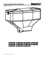
Страница 18: ...Trynex International 2011 REV A F50872 18 Hopper Assembly Parts Breakdown Model SP 1575 7 17 6 10 16 12 20 14 2 1 21 11 3 19 8 4 13 18 5 9 15...

Страница 19: ...ption Qty 1 D4122 4 2 D5100 1 3 D5105 1 4 D5110 1 5 D5114 1 6 D5115 1 BOM ID Description Qty 7 D5706 4 8 D6105 2 9 D6137 2 10 D6140 1 11 D6165 4 12 D6166 4 BOM ID Description Qty 13 D6169 6 14 D6174 1...

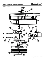
Страница 20: ...Trynex International 2011 REV A F50872 20 Frame Assembly Parts Breakdown Model SP 1575 20 23 23 25 27 3 10 26 18 15 8 14 21 22 4 17 1 19 12 16 5 11 6 9 13 2 7 24...

Страница 21: ...5107 1 4 D5120 1 5 D5138 1 6 D5139 1 7 D5140 1 BOM ID Description Qty 8 D5535 4 9 D6107 1 10 D6131 4 11 D6132 4 12 D6165 1 13 D6172 4 14 D6214 2 BOM ID Description Qty 15 D6232 2 16 D6327 1 17 D6332 1...

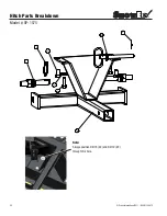
Страница 22: ...Trynex International 2011 REV A F50872 22 Hitch Parts Breakdown Model SP 1575 4 7 1 2 3 8 5 6 Note Always position D4116 2 and D4119 3 through this hole...

Страница 23: ...ernational 2011 REV A F50872 Hitch Parts Breakdown Model SP 1575 BOM ID Description Qty 1 D4115 3 2 D4116 1 3 D4119 1 BOM ID Description Qty 4 D4133 2 5 D4135 1 6 D4136 1 BOM ID Description Qty 7 D413...

Страница 24: ...Trynex International 2011 REV A F50872 24 Hopper Assembly Parts Breakdown Model SP 1875 2 16 4 1 5 6 15 17 7 9 14 11 18 12 10 13 8 3...

Страница 25: ...75 BOM ID Description Qty 1 D4122 4 2 D4124 4 3 D6105 2 4 D6137 6 5 D6140 1 BOM ID Description Qty 6 D6169 10 7 D6174 1 8 D6198 2 9 D6313 1 10 D6314 1 BOM ID Description Qty 11 D6315 1 12 D6328 1 13 D...

Страница 26: ...Trynex International 2011 REV A F50872 26 Frame Assembly Parts Breakdown Model SP 1875 15 7 12 4 17 23 3 26 1 11 22 21 14 10 20 25 19 16 10 8 24 5 18 6 13 27 9...

Страница 27: ...133 1 4 D6172 4 5 D6214 2 6 D6225 1 7 D6232 2 BOM ID Description Qty 8 D6281 1 9 D6317 1 10 D6323 1 11 D6324 1 12 D6325 1 13 D6326 1 14 D6327 1 BOM ID Description Qty 15 D6331 1 16 D6332 1 17 D6333 14...

Страница 28: ...Trynex International 2011 REV A F50872 28 Notes...

Страница 29: ...29 Trynex International 2011 REV A F50872 Notes...

Страница 30: ...Trynex International 2011 REV A F50872 30 Notes...

Страница 31: ...31 Trynex International 2011 REV A F50872 Notes...

Страница 32: ...132609...

Отзывы: