


TruTrak Flight Systems
2
Gemini Autopilot Installation Manual
April 2015
8300-088 Rev IR
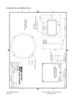
Controller Installation
Mounting Considerations
The Gemini Autopilot controller unit is designed to mount in the aircraft instrument panel within view and reach of the
pilot. Maximum recommended viewing angle should be no more than 20 deg
.
The maximum mounting angle the Gemini
can accommodate is 10 degrees longitudinal (pitch) axis and 0 degrees lateral (roll or yaw) axis. The location should be
such that the controller unit is not blocked by the glare shield on top, or by the throttles, control yoke, etc. on the
bottom. Use aircraft installation standards for mounting and support of the controller.
Wiring Considerations
Use AWG #24 or larger wire for all connections unless otherwise specified. The standard solder pin contacts supplied in
the connector kit are compatible with up to AWG #18 wire. In cases where some installations have more than one
component sharing a common circuit breaker, sizing and wire gauge is based on length of wiring and current draw on
units. In these cases, a larger gauge wire such as AWG #20 may be needed for power connections. Do not attach any
wires to the outside of the programmer or route high current wires within six (6) inch of the controller. Ensure that
routing of the wiring is not exposed to sources of heat, RF or EMI interference. Check that there is ample space for the
cabling and mating connectors. Avoid sharp bends in cabling and routing near aircraft control cables. Do not route the
COM antenna coax near any autopilot components.
Pitot and Static Connections
All multi-servo TruTrak autopilots require connections to the pitot and static lines. The ports on the back of the
autopilot are standard 1/8 NPT size. A single wrap of thread tape is recommended. The preferred method of this
connection would be tee fittings near the aircraft’s altimeter. The static line for the autopilot requires due care in its
construction, as excessive lag or insufficient static orifices can cause the autopilot to oscillate (hunt) in pitch. Although
there is compensation within the autopilot sufficient to handle moderate amounts of lag, the importance of a good static
port and line cannot be overstated. In some cases problems can be caused by having a large number of devices
(including the autopilot) connected to a single, insufficient, static port. In other cases, the static line itself is adequate
but there are one or more devices connected to the same line, one of which has a large static reservoir. A simple remedy
for this problem if it occurs is a tee-fitting near the static port, and a dedicated line to the autopilot only. Obviously, an
insufficiently-large orifice coupled with large static reservoirs can aggravate the problems associated with lag.
RFI/EMI considerations
The autopilot controller is shielded and does not generate any appreciable level of electromagnetic interference.
Moreover, the servo lines (except for power and ground) are low-current and cannot contribute to RF interference. The
servo power and ground lines do have switching currents through them, but so long as there are no parallel runs of
servo power and ground lines with such things as poorly-shielded antenna lines or strobe light power lines, there is no
need to shield the servo harnesses.
The autopilot itself has been internally protected from RF interference and has been tested under fairly extreme
conditions, such as close proximity to transmitting antennas. However, it is always good practice to insure that such
antennas are properly shielded and not routed directly over or under sensitive panel-mounted electronic equipment.
Most problems in this area are the result of improper RF shielding on transmitting antennas, microphone cables, and
the like. The most sensitive input to the autopilot is the Control Wheel Switch input. This line should not be routed in
parallel with transmitting antennas or other sources of known RF interference. If necessary, it can be shielded with the
shield connection to pin 13 of the autopilot connector.
Содержание 8300-088
Страница 19: ......