6
Accessories and consumables
34
6.1
Ordering consumables
35
7
Appendix: Declaration of conformity, guar-
antee, replacement parts lists
36
E681en_02
Table of contents
3
Страница 1: ...Operator s manual TruTool TKF 1500 1A1 1B1...
Страница 2: ...5 Adjusting height of the cutting tool 15 3 6 Select gear 16 3 7 Accessories included 17 Securing the chip box 17 Handle base 18 Tube shaped handle 18 Roller holder 19 3 8 Options 20 Roller holder fo...
Страница 3: ...6 Accessories and consumables 34 6 1 Ordering consumables 35 7 Appendix Declaration of conformity guar antee replacement parts lists 36 E681en_02 Table of contents 3...
Страница 4: ...using the electric tool outside Protect the machine cable in areas where there are sparks Only use original TRUMPF accessories Damage to the machine due to improper handling Wear safety glasses heari...
Страница 5: ...p after machining the workpiece Use the suspension bracket with balancer Use the suspension cable Damage to property due to improper handling Collisions could result from setting the machine incorrect...
Страница 6: ...ended use The TRUMPF TruTool TKF 1500 beveler 1A1 1B1 is an elec trical powered hand held device designed for the following appli cations Preparation of all K V X and Y shaped welding grooves usual fo...
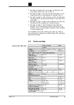
Страница 7: ...0 beveler 1B1 also offers 2 gear changing for modifying the working speed when machining high tensile materials 2 2 Technical data Other countries USA Values Voltage 230 V 120 V 110 V 120 V Frequency...
Страница 8: ...gear 4 1 ft min 1st gear 6 55 ft min 2nd gear Nominal power con sumption 2000 W Nominal current 15 A Stroke rate with nominal load 230 min 1st gear 370 min 2nd gear 170 min 1st gear 340 min 2nd gear 1...
Страница 9: ...n Inch Dimensions e g material thickness chamfer length no Idle speed Revolution speed without load min Revolutions strokes per minute Revolution speed stroke rate per minute Tab 3 2 4 Noise and vibra...
Страница 10: ...ration load during the entire working period Designation of measured value Unit Value according to EN 60745 Vibration emission value ah vector sum of three directions m s2 12 1 Uncertainty K for vibra...
Страница 11: ...6 7 6 6 6 5 6 4 6 3 6 2 6 b 10 6 9 6 8 6 7 6 6 6 5 6 4 6 3 6 2 6 hs 37 5 15 5 13 8 12 2 10 5 8 9 7 3 5 6 4 2 4 ls 9 4 8 4 7 4 6 4 5 4 4 4 3 4 2 4 1 4 b 12 3 11 9 6 8 3 7 5 8 4 4 3 1 1 9 hs 30 15 13 1...
Страница 12: ...angle of bevel 2 Consult the table to find the desired length of bevel ram length ls and the associated scale value W see Tab 5 pg 11 3 Rotate the crank sliding block 65 until the scale value W on the...
Страница 13: ...gon head screw Fig 38120 Notes With stripper 24 the angle of bevel is continuously adjustable between 20 and 45 With stripper 55 order number 0032119 the angle of bevel is adjustable between 20 and 55...
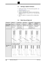
Страница 14: ...clamping screw 23 3 4 Selecting cutting tool Cutting tool Standard High tensile Aluminum High tensile 5575 Heavy duty cut ting tool Order number 0088503 0089335 0005014 0005575 0110399 Application Ge...
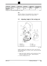
Страница 15: ...ine in the 2 gear version 3 5 Adjusting height of the cutting tool 1 Cutting tool 7 Clamping screw 15 Eccentric shaft 20 Carrier 22 Sliding sleeve 28 Pressure die Fig 13094 Adjust the height of the cu...
Страница 16: ...2nd gear 1st gear can always be worked with but never vice versa Damage to property due to turning the gear switch during operation Damage to the gearbox can be a consequence Use the gear switch only...
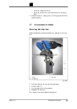
Страница 17: ...on 3 7 Accessories included Securing the chip box Chips that fall away during machining are collected in the chip box 1 Screw 2 Locking bar 3 Chip box Fig 54642 1 Push the chip box 3 onto the clamping...
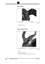
Страница 18: ...s M10x25 2 Handle base Fig 42381 Tighten screws 1 Tube shaped handle 1 Tube shaped handle 2 Screws M10x20 Fig 41795 Note Do not use washers Tighten the tube shaped handle with a screw 2 18 Accessories...
Страница 19: ...the left hand side can be ordered separately 1 When the roller holder is to be installed without a handle base the supplied screws washers and nuts will also be required Note Do not use washers 2 If...
Страница 20: ...essing The roller holder below can be used to bevel tubes with an out side diameter of up to 200 mm The minimum tube inside diam eter must be 100 mm For roller holder for tubes with an outside diamete...
Страница 21: ...er and fasten them to the machine using the screw 4 4 Set the material thickness on a level sheet using the spindle 5 Position the machine on the tube 6 Use the adjusting screw 1 to align both rollers...
Страница 22: ...completely 5 Undo the screw 8 on the lever 6 Remove the pressure die 5 from the special tool 7 Unscrew both screws from the special tool 3 and remove the stripper 4 8 Then retract the special tool int...
Страница 23: ...rews are used for greater material thicknesses These screws are subject to great stress When changing spacers check the cap screws 49 for wear and replace with new screws if necessary For maximum mate...
Страница 24: ...ith spindle 3 Attach the corresponding spacer with spindle 4 Tighten the cap screw with a moment of 250 Nm Tip In order for the machine to run better insert the roller holders for tube processing 24 O...
Страница 25: ...Suspension bracket 1 Clamping screw Suspension bracket Fig 54644 In order to install the suspension bracket on the handle base screw in the clamping screw 1 in the recess E681en_02 Options 25...
Страница 26: ...eveler can be fastened is used for machining small workpieces The workstation can be mounted on a base plate or on a pedes tal The pedestal must be fastened into the floor using a mounting hole Workst...
Страница 27: ...1 Threaded hole Fig 54705 Fasten the machine to the workstation using the screw in the threaded hole 1 E681en_02 Options 27 Mounting the machine at a workstation...
Страница 28: ...s release switch 3 and On switch 1 On switch 1 remains engaged The motor is running 4 To switch the instantaneous connection press the release switch 3 then press the On switch 1 and Off switch 2 toge...
Страница 29: ...e Push the machine carefully as far as possible against the sheet edge i e piercing Slide the machine along the sheet in such away that the machine axis is roughly parallel to the sheet edge Press the...
Страница 30: ...Gearbox and gear head After 300 operating hours arrange for a trained specialist to relubricate or to replace the lubricating grease Lubricating grease G1 0139440 Pressure die Clean as needed Cutting...
Страница 31: ...plug from the plug socket before undertaking any maintenance work on the machine Damage to property due to improper handling Collisions could result from setting the machine incorrectly Rotate the ec...
Страница 32: ...towards the bottom 4 Screw out the cutting tool 1 5 Grease the square part of the cutting tool and the bore hole of the carrier slightly with S1 lubricating grease order num ber 0121486 6 Check the p...
Страница 33: ...Rotate supporting body 20 by 45 3 Pull the carrier out towards the top 4 Screw out the cutting tool 1 5 Undo the cap screw 23 pull the sliding sleeve 22 up and out of the supporting body 20 6 Slide th...
Страница 34: ...h tensile mate rials 10 pack 1264432 Sliding sleeve cutting tool guide 0038351 X Stripper replacement part for roller holder and for special tool 0023242 Consumables Tab 10 TruTool TKF 1500 1A1 1B1 Or...
Страница 35: ...032119 Punching and nibbling oil for aluminum 1 l 0125874 Lubricating grease S1 1000 g 0342887 Lubricating grease G1 900 g 0139440 Accessories Tab 11 6 1 Ordering consumables Note The following data m...
Страница 36: ...7 Appendix Declaration of conformity guarantee replacement parts lists 36 Appendix Declaration of conformity guarantee replacement parts lists E681en_02...