


20
Advice on water installation
• You need practical experience to make con-
nections using push-fit systems (e.g. John
Guest or equivalent).
• As regards furnace operation, pressure
pumps and submersible pumps operating
at pressures as high as 40.6 psi (2.8 bar) as
well as hot/cold mixing faucets with or with-
out an electrical switch can be installed.
• If you use a water pump with a pressure
higher than 40 psi (2.8 bar) or if you connect
your system to a city water supply, you must
first install a pressure reducer so that pres-
sure in the water container will not exceed
40 psi (2.8 bar).
• The thermal expansion of water during
heating can result in pressures as high as
65.25 psi (4.5 bar) before the pressure relief/
drain valve responds.
• Water lines connected to the water container
and the drain valve must withstand tempera-
tures in excess of 176 °F (80 °C). They must
also be suitable for potable water and must
withstand pressures as high as 65 psi (4.5 bar).
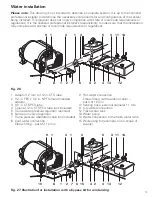
• If a submersible pump is used, you must in-
stall a non-return valve (Fig. 26 – 6) between
the pump and the first branch.
• If you use pressure pumps that exhibit con-
siderable switching hysteresis, hot water
can flow back via the cold water faucet. You
must install a non-return valve (Fig. 26 – 6)
between the outlet to the cold water faucet
and the pressure relief/drain valve to prevent
backflow. Install the water lines so as to en-
sure that all connected components function
as intended. More specifically, water lines
must be as short, kink-free, and unstressed
as possible.
• Lay cold water lines higher than the pressure
relief/drain valve.
Non-compliance will
void warranty claims for frost damage.
• There must be a clearance of 1 in. (2.5 cm)
between water lines and sources of heat.
• The furnace’s cold water supply must not come
into contact with cold bridges such as the RV’s
side wall on account of the risk of frost.
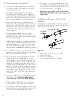
• An adaptor must be installed at every junc-
tion between a 12 mm push-fit system and
a 1/2 in. CTS tube; see”Installing a 12 mm /
1/2 in. CTS adaptor” on page 20.
•
All hose connections must be secured
by means of clamps or crimp rings, even
cold water.
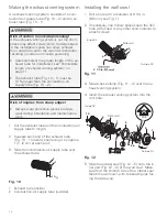
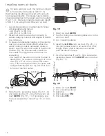
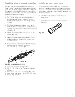
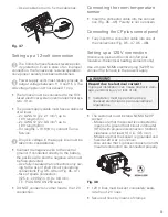
Installing a 12 mm / 1/2 in. CTS
adaptor
An adaptor must be installed at every junction
between a 12 mm push-fit system and a 1/2 in.
CTS tube; see Fig. 28 – 1.
12 mm
Adaptor
1/2 in. CTS tube
2
1
3
1 in. (25 mm)
Fig. 28
1 Adaptor 12 mm to 1/2 in. CTS tube
2 1/2 in. CTS tube
3 Clamp or crimp ring
(not included in scope of delivery)


