

2
Table of Contents
Trademark information
........................................................ 2
Intended use
.......................................................................... 2
Prohibited use
........................................................................ 2
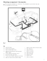
Mounting arrangement / Accessories
................................ 3
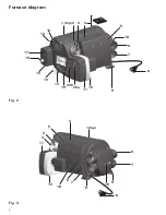
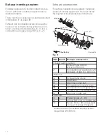
Furnace diagram
.................................................................... 4
Installer Safety Information
Safety symbols and signal words
...................................... 6
Safety behavior and practices
............................................. 6
Installation Instructions
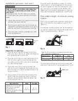
Selecting an installation space
........................................... 7
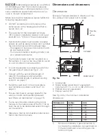
Dimensions and clearances
................................................. 8
Dimensions ............................................................................... 8
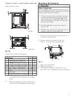
Clearance from combustible materials .................................... 9
Securing the furnace
............................................................ 9
Exhaust venting system
..................................................... 10
Exhaust accessories ............................................................... 10
Installation position: wall cowl ............................................... 11
Permissible length of exhaust venting system ....................... 11
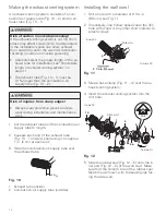
Making the exhaust venting system ...................................... 12
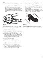
Installing the wall cowl ........................................................... 12
Connecting the exhaust venting system
to the Combi furnace .............................................................. 14
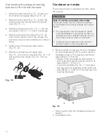
Circulated air intake
............................................................ 14
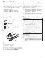
Warm air distribution
......................................................... 15
Parts for warm air distribution ................................................ 15
Warm air outlets ..................................................................... 15
Permissible warm air ducts .................................................... 15
Installing warm air ducts ........................................................ 16
Installing end outlets .............................................................. 17
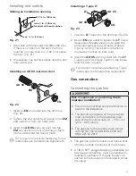
Gas connection
.................................................................... 17
Connecting the gas line .......................................................... 17
Checking for gas leaks ........................................................... 18
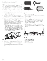
Water installation
................................................................ 19
Advice on water installation ................................................... 20
Installing a 12 mm / 1/2 in. CTS adaptor ................................ 20
Installing a water pressure regulator ...................................... 21
Installing a non-return valve ................................................... 21
Installing a pressure relief/drain valve .................................... 22
Laying water lines .................................................................. 22
Connecting the water container ............................................. 22
Final tasks ............................................................................... 23
Installing the CP plus control panel
................................. 23
Installing the room temperature sensor
.......................... 23
Electrical connections
....................................................... 24
Setting up a 12-volt connection ............................................. 25
Connecting the room temperature sensor ............................. 25
Connecting the CP plus control panel .................................... 25
Setting up a 120 V connection ............................................... 25
Final tasks
............................................................................ 26
Warning labels
..................................................................... 26
System checks
..................................................................... 26
Functional test
..................................................................... 26
Ignition control test ................................................................ 26
Static pressure test ................................................................. 27
Final check of installation
.................................................. 27
Connection diagram 12 volt (Control_PCB)
.................... 28
Connection diagram 120 volt AC (120 VAC_E_PCB)
..... 29
Appendix A
........................................................................... 30
Appendix B
........................................................................... 31
Appendix C
........................................................................... 34
Trademark information
Truma Combi® referred to as Combi below.
Intended use
The Combi LP gas furnace* with supplemen-
tary indirect water heating may be used only in
recreational vehicles (RVs) for heating the room
and the faucet water.
Recreational vehicles (RVs) are designed as
temporary living quarters for recreation, travel
and/or camping. RVs have their own power or
are towed by another vehicle.
*Models
• Combi
eco
• Combi eco plus
• Combi
comfort
• Combi comfort plus
The Combi eco plus and Combi comfort plus
furnaces also feature electrical heating elements
for a supply voltage of 120 V.
Prohibited use
Any use other than the intended use (see above)
is prohibited.
Examples of prohibited use:
• Use in a marine environment.
• Use as part of a space heating system.
• Use in mobile homes.
• Use in food trucks or roadside food vending
vehicles.
• Use in construction trailers.


