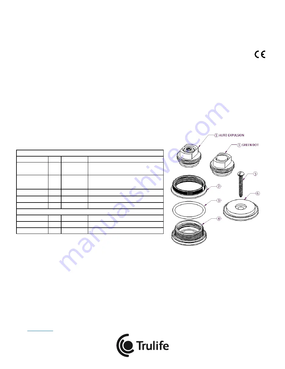
AEV350, MEV350
TWO PART VALVE HOUSING,
AUTO AND MANUAL EXPULSION
Installation and User Guide
32210-001 REV A
Trulife
www.trulife.com
Page 1 of 4
INTRODUCTION
The AEV350 and the MEV350 valves are intended for transfemoral prosthetic suction sockets. Both utilize the same two-part valve
housing, which is ideal for use with flexible thermoplastic socket materials.
The AEV350 valve insert has automatic air expulsion function and manual push button to release suction.
The MEV350 valve has a push button used to manually expel air and to release suction.
Both type valve inserts are removable to allow use of a pull-sock for donning the socket.
Both are furnished with valve key and necessary components to form the socket to accept the two-part valve housing.
Product Code
Description
AEV350
AUTO EXPULSION VALVE WITH TWO-PART HOUSING
MEV350
MANUAL EXPULSION VALVE WITH TWO PART HOUSING
PRODUCT CONTENTS:
ITEM
QTY
PART #
DESCRIPTION
1
(AEV350)
1
32201-001
AUTO EXPULSION VALVE INSERT
ASSEMBLY
1
(MEV350)
1
32213-001
MANUAL EXPULSION VALVE INSERT
ASSEMBLY
2
1
32207-002
SOCKET OUTER HOUSING
3
1
32212-001
O-RING, SIZE -125
4
1
32208-001
SOCKET INNER HOUSING
FABRICATION / ADDITIONALCOMPONENTS :
5
1
24437-001
SCREW, SIZE #8 X 1.25" LONG
6
1
32209-001
FORMING TOOL
7
1
19774-001
VALVE KEY ASSEMBLY (NOT SHOWN)
INSTALLATION AND USE
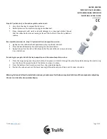
Recommended installation and use procedures must be followed for maximum safety and service life.
Socket Preparation:
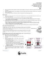
1.
Determine valve location on the positive model. Flatten the region so the forming tool is flush. Mark the center hole
location of the forming tool.
2.
Drill a Ø3.2mm (Ø1/8”) pilot hole for the supplied screw.
3.
Drill a vacuum channel hole 12mm (1/2”) adjacent to the pilot hole with a long drill. This hole must extend through the
model so that vacuum will draw at the forming tool site.
4.
Secure the forming tool to the model with the supplied screw, and positioning it so that one of the small holes in the
forming tool is over the vacuum channel hole.
5.
Vacuum form the thermoplastic socket. Manually apply the necessary external pressure around the forming tool to help
guide the softened thermoplastic to fully form around the tool.


