background image

CHAPTER 2: ASSEMBLY INSTRUCTIONS 

TREADMILL ASSEMBLY STEPS (continued): 

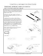
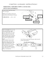
STEP 4: Console Rack and Motor Cover Installation: 

a

) Install Console Rack (A) onto

Pedestals R & L by resting Console

Rack tubing on top of Pedestal tubing

cradles.

b

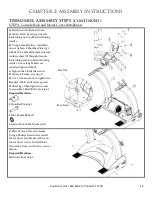
) Using 5 mm Hex Key, install but

do not tighten, 8 Shoulder Plates (g),

8 Bolts-M8 x 40mm (f) and 8 internal

tooth washers (d) through Console

Rack tubing and into Pedestal tubing

cradles. Once all eight bolts are

installed, tighten all bolts.

c

) Tighten the 8 Bolts that secure

Pedestals to Frame. (see step 2) 

d

) Use a 17mm wrench to tighten two

Hex Head Bolts until secure against

Pedestal legs. Then tighten two nuts

to secure Hex Head Bolts. See Fig 4-1.

Required Hardware:

8 Shoulder Plates (g) 

8 M8 x 40mm Bolts (f) 

8 Internal Tooth M8 Washers (d) 

e

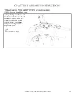
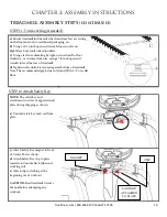
) Place Motor Cover onto frame.

Using a Phillips Screwdriver, install

Motor Cover into Frame with seven

Motor Cover screws. Install Motor

Decoration Covers with two screws as

shown.

Required Hardware:

Hardware from step 1.

Hex Nut 

Hex Screw 

Truefitness.com / 800.426.6570 / 636.272.7100 

14


Содержание TC400

Страница 1: ... Assembly Guide Warranty Card Included Revision 052418 C400 TREADMILL OWNER S MANUAL T Transcend Console Escalate9 Console Emerge Console ...

Страница 2: ...ﻣﻧﺗﺟﺎت ھﻲ اﻟﻣﻌروﺿﺔ اﻟﻧﻣوذج ﺗﺧﺗﻠف ﻗد اﻟﻔﻌﻠﻲ اﻟﻣﻧﺗﺞ ﺗﺳﻠﯾﻣﮭﺎ و اﻟﻣﻧﺗﺞ ﻣواﺻﻔﺎت واﻟﺑراﻣﺞ اﻟﻣﯾزات ﻟﻠﺗﻐﯾﯾر ﻗﺎﺑﻠﺔ إﺷﻌﺎر دون ﻟ ﯾﺻل ﻣﺎ ﻣﻌظم اﻵن ﺣﺗﻰ اﻟﻣﺎﻟك دﻟﯾل زﯾﺎرة ﯾرﺟﻰ www truefitness com ﻟﻠﻣﺳﺗﻧدات ﻟﻐﺎت ﻓﻲ ﯾرﺟﻰ إﺿﺎﻓﯾﺔ زﯾﺎرة www truefitness com document library 29 international manuals WICHTIG Alle hier gezeigten Produkte sind Prototypen Das tatsächliche Produkt ausgeliefert wird kann variieren Produkt Sp...

Страница 3: ...l product line has made TRUE successful and is a trademark of the TRUE heritage TRUE s patented Heart Rate Control technology is just one of the remarkable ways we deliver simple and superior performance every user can enjoy and most importantly use to achieve personal health and fitness goals TRUE strives to perfect biomechanically correct and orthopedically comfortable functional products Whethe...

Страница 4: ...l Overview 20 Chapter 4 Care Maintenance 22 22 23 24 24 25 25 25 26 26 27 Care Maintenance Cleaning the Equipment Running Belt Alignment Tensioning the Running Belt Treadmill Lubrication Leveling the Treadmill Other Scheduled Preventive Maintenance Long Term Storage Chapter 5 Customer Service Contacting Service Contacting Sales Reporting Freight Claims or Parts Damage Chapter 6 Additional Informat...

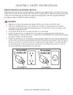
Страница 5: ...g with wet hands WARNING To reduce the risk of burns fire electric shock or injury it is imperative to connect each product to a properly grounded 110V electrical outlet A risk of electrical shock may result from improper connection of the equipment s grounding conductor Check with a qualified electrician if you are unsure about proper grounding techniques Do not modify the plug provided with this...

Страница 6: ...le to the user Keep the power cord away from heated surfaces Do not pull the equipment by the power cord or use the cord as a handle Do not run the power cord along the side or under the treadmill If the electrical supply cord is damaged it must be replaced by the manufacturer an authorized service agent or a similarly qualified person to avoid a hazard Do not use this product in areas where aeros...

Страница 7: ... of bystanders being struck or caught between moving parts by making sure that they are out of reach of the equipment while it is in motion This appliance can be used by children aged from 8 years and above and persons with reduced physical sensory or mental capabilities or lack of experience and knowledge if they have been given supervision or instruction concerning use of the appliance in a safe...

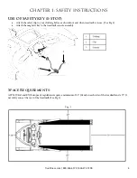
Страница 8: ...when treadmill is in use See Fig 2 Attach the magnetic key to the treadmill console assembly Space Requirements ASTM USA and EN European regulations require a minimum of 20 0 5m on each side of the treadmill and a 79 2 m safety zone at the rear of the treadmill See Fig 1 3 Truefitness com 800 426 6570 636 272 7100 4 2 1 ...

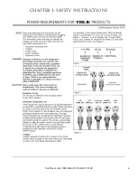
Страница 9: ...the outlet have a proper outlet installed by a qualified electrician Do not remove the motor cover or you may risk injury due to electric shock The 120 V model is for use on a nominal 120 V circuit and has a grounding plug that looks like the plug illustrated in figure A Make sure the product is connected to an outlet having the same configuration as the plug No adaptor should be used with this pr...

Страница 10: ...CHAPTER 1 SAFETY INSTRUCTIONS Truefitness com 800 426 6570 636 272 7100 6 ...

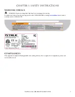
Страница 11: ...e any worn or missing warning decals contact TRUE FITNESS by visiting www truefitness com or contact customer service at 800 883 8783 COMPLIANCES This equipment complies with all applicable codes and regulations For a complete list of compliances please visit www truefitness com Truefitness com 800 426 6570 636 272 7100 7 ...

Страница 12: ...to your treadmill and enhances your safety by helping to prevent shock Check with a qualified electrician or serviceman if you are in doubt as to whether the treadmill is properly grounded Do not modify the plug provided with the treadmill if it will not fit the outlet Have a proper outlet installed by a qualified electrician Read and understand all instructions and warnings prior to use Obtain a ...

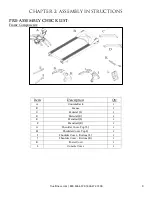
Страница 13: ...cription Qty A Console Rack 1 B Frame 1 C Pedestal L 1 D Pedestal R 1 E Handrail L 1 F Handrail R 1 G Shoulder Cover Top L 1 H Shoulder Cover Top I 1 I Shoulder Cover Bottom L 1 J Shoulder Cover Bottom R 1 K Power Cord 1 L Console Cover 1 Truefitness com 800 426 6570 636 272 7100 9 ...

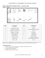
Страница 14: ...d Belt Lubricant 1 Under Tread belt i T Spanner 8mm 1 Tread Belt Adjustment j Wrench 17mm 1 Hex Head Bolt Pedestal Front k Hex Key 5mm 1 Various NOTE Consult your TRUE Fitness TCS400 Treadmill Owner s Manual for information related to item h Tread Belt Lubricant for Tread Belt lubrication procedure and item i T Spanner 8mm for Tread belt Adjustment Tool Requirements Hex Key 5mm T Spanner 8 mm Wren...

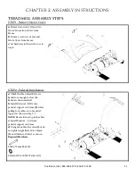
Страница 15: ...ad Bolts are backed out enough to clear the Pedestals when installed b Install Pedestal R D into pedestal support on Frame B while pulling four cables out of pedestal support as shown in Fig 2 1 NOTE Be careful not to pinch cables c Install Pedestal L C into pedestal support on Frame d Using 5mm Hex Key install but do not tighten eight Bolts M8 x 75mm b and Washers M8 d as shown Required Hardware ...

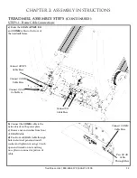
Страница 16: ...er plate c Remove nut and washer from front of COAX Cable d Pass front of COAX Cable through hole in electrical panel and install washer and tighten nut using 1 2 inch open end wrench on nut and long nose pliers on connector portion of cable Connect COMM Cable Here Pass COAX Cable Through Here Truefitness com 800 426 6570 636 272 7100 12 Connect COMM Cable Here Connect COAX Cable Here Connect AUXP...

Страница 17: ...hree screws M5 x 8 for later in this step c Install the 220V power inlet assembly as follows Disconnect the wires one at a time as you transfer them from the original 110V panel to the 220V panel Note The 220V panel has a green blue and a brown color dot on it The colored dots correspond to which color cables should be installed at those locations Begin moving the GREEN YELLOW wire over to the GRE...

Страница 18: ...ght bolts are installed tighten all bolts c Tighten the 8 Bolts that secure Pedestals to Frame see step 2 d Use a 17mm wrench to tighten two Hex Head Bolts until secure against Pedestal legs Then tighten two nuts to secure Hex Head Bolts See Fig 4 1 Required Hardware 8 Shoulder Plates g 8 M8 x 40mm Bolts f 8 Internal Tooth M8 Washers d e Place Motor Cover onto frame Using a Phillips Screwdriver in...

Страница 19: ...ation a Insert Handrails E F onto Pedestals and secure with 4 Bolts M8 x 80mm c and Internal Tooth Washer M8 d using 5 mm Hex Key Required Hardware 4 M8 x 80mm bolts c 4 Internal Tooth M8 Washers d STEP 7 Top Shoulder Covers a Using a Phillips screwdriver install Shoulder Cover Top pieces Left G and Right H with three Screws M4 x 10mm c on each side as shown CAUTION Make sure cabling is NOT pinche...

Страница 20: ... Covers a Using a Phillips screwdriver install Shoulder Cover Bottom pieces Left I and Right J with five Screws M4 x 10mm c on each side as shown CAUTION Make sure cabling is NOT pinched during installation Required Hardware 10 M4 x 10mm screws c Truefitness com 800 426 6570 636 272 7100 16 ...

Страница 21: ...ess com 800 426 6570 636 272 7100 17 STEP 9B Rear Console Cover Place the two bottom console mounting screws inside the bottom keyholes on the console mast assembly Partially thread the two top console mounting screws into the console Fully tighten all four console mounting screws Note Ensure all cable connections are routed inside the console mast assembly to prevent cable pinching Note Refer to ...

Страница 22: ...s should occur please wait 10 minutes and then reset the Circuit Breaker by rocking the power switch fully to the OFF position O and then rocking the power switch back to the ON position If it does not reset or the Circuit Breaker operates again udner normal use contact True Fitness at 1 800 883 8783 Circuit Breaker Positions Note The above picture shows the power switch in the OFF position O for ...

Страница 23: ...ill Owner s Manual before attempting any workout LANYARD ATTACHED TO PLATE CLIP MAGNET Truefitness com 800 426 6570 636 272 7100 19 STEP 12 Attach Safety Key a Ensure treadmill incline rack wheels and rear feet are resting on the floor and not on cardboard packaging etc b Using a 15 16 inch open end wrench loosen nut A on Right Rear Foot only side adjustable c Using a level or estimating by sight ...

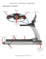
Страница 24: ...CHAPTER 3 PRODUCT OVERVIEW TREADMILL OVERVIEW Console Assembly Straddle Covers Belt Leveling Feet On Off Switch Circuit Breaker and Power Cord Belt Adjustment Bolts Contact Heart Rate Pad Contact Heart Rate Pad Safety E Stop Key Quick Access Keys ...

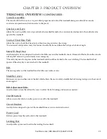
Страница 25: ...e will stop belt motion to prevent injury in an emergency The safety key must be in place on the treadmill and should be attached to the user s clothing The treadmill will not operate if the safety key is not attached to the treadmill Belt The moving surface of the treadmill on which the user walks or runs Straddle Covers Stationary covers on either side of the belt which allows the user to safely...

Страница 26: ...LEANING THE EQUIPMENT After Each Use Use GymWipes Antibacterial wipes or spray a solution of 30 parts water to 1 part mild detergent to dampen a soft cloth and wipe all exposed surfaces Use a LCD screen cleaner or spray a solution of 1 part 91 isopropyl alcohol and 1 part water to dampen a soft cloth and wipe the surface of the console This helps remove fingerprints dust and dirt Weekly Vacuum any...

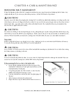
Страница 27: ... on the running deck If the belt drifts off center you must make adjustments Important Failure to align the belt may cause the belt to tear or fray which may not be covered under the TRUE Fitness Warranty To stop the running belt press the STOP key Turn the treadmill off CAUTION For your safety use the power switch to turn off the treadmill before making any adjustments Do not adjust the running b...

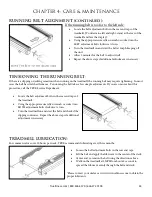
Страница 28: ...e belt takes a few simple adjustments If you are unsure about this procedure call the TRUE Service Department Locate the belt adjustment bolts in the rear end caps of the treadmill Using the appropriate size Allen wrench or socket turn BOTH adjustment bolts clockwise turn Turn the treadmill on and start the belt and check if the slipping continues Repeat the above steps if additional adjustment is...

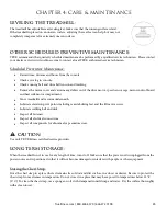
Страница 29: ...mpartment Move treadmill and vacuum underneath Lubricate elevation pivot points including rear stabilizing feet and the lift motor screw Lubricate walking belt and deck Inspect all fasteners Inspect all electrical connections Inspect all components for abnormal or premature wear CAUTION Use only TRUE Fitness certified service providers LONG TERM STORAGE When the treadmill is not in use for any len...

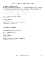
Страница 30: ...may also contact TRUE Fitness customer support team by calling 800 883 8783 or e mailing us at service truefitness com Monday Friday during normal business hours TRUE FITNESS SERVICE DEPARTMENT 865 HOFF ROAD ST LOUIS MO 63366 1 800 883 8783 HOURS OF OPERATION 8 30 A M 5 00 P M CST E MAIL service truefitness com CONTACTING SALES Interested in TRUE Products Please contact us with any sales or produc...

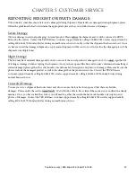
Страница 31: ...r not You must sign the bill of lading as damaged when accepting the shipment Once you have opened the box and you have determined something is indeed damaged please gather the serial number model number description and photos of damages Please make sure the photos include the damaged product as well as the damaged box the product arrived in Contact the TRUE Fitness customer support team by callin...

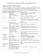
Страница 32: ...wer cord not fully seated in socket Inspect power connection at the unit and outlet Safety e stop key not fully engaged Re engage the safety e stop key to the console Insufficient power Verify output voltage from 20A outlet with a voltmeter Error code is displayed on console Contact TRUE Fitness Customer Service Department Pinched or loose main communication cable No User Present displayed on scre...

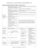
Страница 33: ...stable If the probable source of interference is plugged into the same outlet move the suspect source to another outlet Environmental interference from computers Environmental interference from motor driven appliances Environmental interference from cell or cordless phone Environmental interference from Wi Fi router Fault Code Category Description Cause Corrective Action Fault CN00 Corrupted Conso...

Страница 34: ...C Voltage at Outlet Fault CN08 Calibration Failed Lower Limit Not Reached Console During incline calibration the incline stalled before reaching what should be the lower limit Console displays Fault Calibration not saved Incline disabled Power cycle Check cable connections Run incline calibration Incline Potentiometer value out of range Contact dealer or TRUE service Fault CN09 Insert Safety Key C...

Страница 35: ...d data Dirty or misaligned speed sensor Contact dealer or TRUE service High Belt Deck Friction Lubricate treadbelt Contact dealer or TRUE service Low Line Voltage Check AC line voltage Fault IN01 Incline Stall Incline Incline not moving when commanded Console displays Fault Calibration not saved Incline disabled Power cycle Check cable connections Run incline calibration Incline Potentiometer valu...

Страница 36: ...ions Motor Control Board Contact dealer or TRUE service Fault A105 Motor Controller Fault AC MCB Phase C Circuit Open Loose Cable Check cable connections Motor Control Board Contact dealer or TRUE service Fault A106 Motor Controller Fault AC MCB Phase B Circuit Open Loose Cable Check cable connections Motor Control Board Contact dealer or TRUE service Fault A107 Motor Controller Fault AC MCB Phase...

Страница 37: ...age Check AC line voltage Fault A115 Motor Over Temp AC MCB Over Temperature on Motor Drive High Belt Deck Friction Lubricat treadbelt Contact dealer or TRUE service Low Line Voltage Check AC line voltage Fault A116 Motor Controller Fault AC MCB Brake Gate Driver Fault Loose Cable Connection Check cable connections Drive Motor Contact dealer or TRUE service MCB Fault A117 Motor Controller Fault AC...

Страница 38: ...ntact dealer or TRUE service MCB Fault A125 Motor Controller Fault AC MCB Phase C Current Sensor Loose Cable Connection Check cable connections Drive Motor Contact dealer or TRUE service MCB Fault A126 Motor Controller Fault AC MCB PFC Driver Fault Loose Cable Connection Check cable connections Drive Motor Contact dealer or TRUE service MCB Fault A127 Motor Controller Fault AC MCB Elevation Peak O...

Страница 39: ...CHAPTER 6 ADDITIONAL INFORMATION WIRING DIAGRAMS Truefitness com 800 426 6570 636 272 7100 35 ...

Страница 40: ...CHAPTER 6 ADDITIONAL INFORMATION WIRING DIAGRAMS Truefitness com 800 426 6570 636 272 7100 36 ...

Страница 41: ...d for defects in material and workmanship for three years with two years labor warranty This limited warranty does not cover damage or equipment failure resulting from or caused by improper assembly installation failure to follow instructions and warnings in owner s manual accident misuse abuse unauthorized modification or failure to provide reasonable and necessary maintenance TRUE Fitness shall ...

Страница 42: ...pment failure resulting from or caused by improper assembly installation failure to follow instructions and warnings in owner s manual accident misuse abuse unauthorized modification or failure to provide reasonable and necessary maintenance as referenced in the owner s manual 6 This Limited Warranty applies only to the cost of repair or replacement of parts and does not include labor beyond the a...

Страница 43: ... on a daily basis ___ a 25 ___ b 25 75 ___ c 76 150 ___ d 150 6 Do you plan to purchase more fitness equipment in the next 6 12 months ____ Yes ____ No 7 If you answered yes to question 6 what type do you plan to purchase ____ a Treadmill ____ b Elliptical ____ c Stationary Bike ____ d Free Weights ____ e Gym ____ f Other ______________ 8 Would you recommend TRUE to other club owners ____ Yes ____...

Отзывы: