10 Manual Number 9017942 • Revision K, May 14, 2020
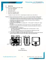
1.50
1.000
1.50
0.600
4-40 UNC-2B
2 plcs
0.640
0.700
0.955
0.125
3.4
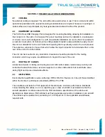
MOUNTING
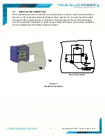
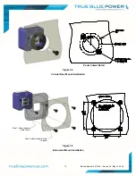
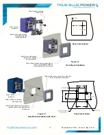
The TA102 can be installed in one of four ways:
rear mount, rectangular
rear mount, circular *
instrument mount *
front mount, decorative bezel *
rear mount, decorative bezel *
* installation kit required. See Section 3.2, Optional Equipment Available for part number reference
Prepare the panel cutout as shown in Figures 3.3, 3.4, 3.5 or 3.6 per the selected mounting option.
For Rectangular Rear Mount, Circular Rear Mount and Instrument Mount Installations
countersinks in the panel for flat head screws are optional. However, flat head screws are
provided for flush appearance. For Front and Rear Decorative Bezel Installations,
countersinks in the panel are required.
For Rear Mount Installations:
Mounting screws length MUST be between (PT + 0.150”) and (PT +0.260”). [PT = panel
thickness]
Mounting screws provided with the unit are 0.24” and 0.31” (accommodates 0.020” to
0.160” PT). For PT greater than 0.125, the USB connector will be below the surface of
the panel (below flush).
For Circular Rear Mount Installations:
Mounting screws length MUST be between (PT + 0.200”) and (PT + 0.375”).
[PT = panel thickness]
Mounting screws provided with the Circular Rear Mount Install Kit are 0.438”.
For Front Mount Installation: Maximum panel thickness is 0.25”.
For Rear Mount Installation with Decorative Bezel: Panel thickness greater than 0.065 will
cause the USB connector to be below the surface of the bezel (below flush).
Figure 3.2
TA102 Outline Drawing
Содержание TA102
Страница 1: ...Revision K May 14 2020 ...


