background image

Page 6

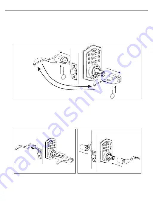
11. REMOVING AND REVERSING LEVER HANDLES

  a. Make sure the Door Lock is in the unlocked position and then release catch by  

  inserting Lock Stick into the slot on the underside of levers (Figure 11a).

  b. Remove both lever handles from the bases by pulling away from door when the catch  

  is released (Figure 11b).

  c. Switch the lever handles to the opposite side (Figure 11c).

12. REPLACING LEVER HANDLES

  a. Make sure lock cylinder is in line with handle (Figure 12a).
  b. Replace handles by sliding onto the bases until the catch pins are engaged.    

  (Figure 12b). 

REVERSIBLE LEVER HANDLES

Reversible handle

Interchangeable 

Cylinder

Lock Stick

Lock Stick

Figure 11a-c

Figure 12a

Figure 12b

Содержание M1740024

Страница 1: ...M1740024 1740026 1740028 1740030 V2 Classic Electronic Lever...

Страница 2: ...NSTRUCTIONS Exterior Assembly Overview Page 8 Locking and Unlocking Changing Programming Code Adding User Codes Page 9 Deleting User Codes Automatic Lock Function Temporarily Disable Auto Lock Page 10...

Страница 3: ...1 8 54mm Drill Hole Saw 1 25mm Drill 1 16 2mm Drill Chisel Hammer Phillips Screwdriver DO NOT RETURN TO STORE If any parts are missing or damaged please call Customer Service toll free at 1 877 354 54...

Страница 4: ...Insert Latch in hole keeping it parallel to face of door Mark outline and remove Latch Figure 3c d Chisel 1 8 3mm deep or until latch face is flush with door edge Figure 3d 4 MARK AND DRILL DOOR JAMB...

Страница 5: ...the door with a hand held screwdriver DO NOT OVER TIGHTEN Figure 5b ADJUSTING LATCH NOTE Latch is shipped with the backset set at 2 3 8 60mm Measure the backset backset is distance between edge of th...

Страница 6: ...t hole in your door using the Mounting Plate upper hole as a guide Figure 8a b Insert one 3 4 19mm screw C and tighten Mounting Plate C 3 4 19mm screw Optional B 7 8 22mm screws Control Wire Figure 8a...

Страница 7: ...Figure 9c d The Control Wire male plug is inserted with the smooth side up into the Interior Assembly female socket connector Figure 9d 10 ATTACH THE INTERIOR ASSEMBLY TO DOOR a Position the Interior...

Страница 8: ...the bases by pulling away from door when the catch is released Figure 11b c Switch the lever handles to the opposite side Figure 11c 12 REPLACING LEVER HANDLES a Make sure lock cylinder is in line wit...

Страница 9: ...using the Interior Lever The Latch should move smoothly b Test the lock using the Keypad To lock press and then press 1234 to unlock INSTALLING INTERIOR ASSEMBLY CONT NOTE Do not touch the Keypad unti...

Страница 10: ...lear Used to clear wrong keypad entries Unlock Used to unlock door Programming Used in programming steps LOCK BUTTON UNLOCK BUTTON FACTORY SETTINGS The lock comes factory preset with a Please change t...

Страница 11: ...digit combination Each User Code is then linked to a User ID which is any number between 01 50 to identify an individual User Code User ID 1 9 should be entered as 01 09 so they are 2 digits Hear 1 b...

Страница 12: ...ates green To cancel Auto Lock set the time to 00 enter the following Cancel Time Value Auto Lock Hear 1 beep and Light Indicator illuminates green Hear 1 beep and Light Indicator illuminates green 2...

Страница 13: ...ase active Programming or User Codes With Vacation Mode enabled the system enters into low power consumption mode During this mode all buttons and functions including the remote control will be invali...

Страница 14: ...ow Voltage 4 short beeps and LED flashes red four times 4 Incorrect code entry attempts 2 short beeps and LED illuminates red each attempt Power on 1 long beep and 1 short beep and LED illuminates gre...

Страница 15: ...sticking Installation screws of the lock may be too tight and have to be loosened Remove Interior Assembly Slightly loosen the Mounting Plate Screws Lock and unlock using the Key Reattach Control Wir...

Страница 16: ...Page 14 Page Intentionally Left Blank...

Страница 17: ...4 70mm BACKSET THEN DRILL 1 25mm HOLE IN CENTER DOOR OF EDGE 2 50mm IN DEPTH MARK FOR 1 3 4 45mm DOOR DRILL 2 1 8 54mm HOLE MARK FOR 1 3 8 35mm DOOR IMPORTANT PLACE TEMPLATE ON HIGH EDGE OF DOOR BEVEL...

Страница 18: ...Page 16 BACK OF TEMPLATE...

Страница 19: ...Fri Subject to change CALL BACK HOURS Other Countries 7am 5pm Pacific Mon Fri Subject to change Pacific Local time in Los Angeles CA USA Local Time based on Los Angeles California USA DO NOT RETURN TO...

Страница 20: ...costs and shipping and freight expenses required to return product s In no event shall Tru Bolt be liable for any special incidental or consequential damages If this product s is considered a consume...

Отзывы: