background image

1

Safety 

................................................................

 6

1.1  General safety notes .................................  6
1.2  Correct use ................................................  6
1.3  Qualified staff .............................................  6

2

Technical data 

..................................................

 7

2.1  General data ..............................................  7
2.2  FKA2-EU with fusible link ..........................  9
2.3  FKA2-EU with spring return actuator .......  12
2.4  FKA2-EU with spring return actuator and

duct smoke detector ................................  19

2.5  FKA2-EU with fusible link and cover grille

used as an air transfer unit ......................  20

2.6  FKA2-EU with spring return actuator and

duct smoke detector used as an air

transfer damper .......................................  21

3

Supply package, transport and storage 

......

 22

4

Installation 

......................................................

 23

4.1  Installation situations ...............................  23
4.2  Safety notes regarding installation ..........  27
4.3  General installation information ...............  27
4.4  Solid walls ...............................................  38
4.4.1  Mortar-based installation ......................  39
4.5  Lightweight partition walls and compart-

ment walls with metal support structure ..  40

4.5.1  Dry mortarless installation with installa-

tion kit ES .............................................  44

4.5.2  Dry mortarless installation with fire batt

...............................................................  47

4.6  Fixing the fire damper ..............................  50
4.6.1  General .................................................  50
4.6.2  Suspending fire dampers installed

remote from solid walls and ceiling slabs

...............................................................  51

4.6.3  Fixing the damper when a fire batt is

used ......................................................  52

5

Electrical connection 

....................................

 55

5.1  Limit switches (fire dampers with fusible

link) ..........................................................  55

5.2  Spring return actuator ..............................  55
5.3  Spring return actuator and duct smoke

detector RM-O-3-D ..................................  55

6

Functional test 

...............................................

 56

6.1  Fire damper with fusible link ....................  56
6.1.1  Fusible link – size 1 ..............................  56
6.1.2  Fusible link – size 2 and 3 ....................  57
6.2  Fire damper with spring return actuator ..  60
6.2.1  Spring return actuator – BFL... / BFN...

...............................................................  60

6.3  Functional test with automatic control unit

..................................................................  62

7

Commissioning 

..............................................

 63

8

Index

................................................................

 64

Table of contents


Fire damper Type FKA2-EU

5

Содержание FKA2-EU

Страница 1: ...nd operating manual Read the instructions prior to performing any task according to Declaration of Performance DoP FKA2 EU DE 002 GB en Short version This is a content reduced short version The full version is available at www trox docs com ...

Страница 2: ...on of the original 2020 TROX GmbH Heinrich Trox Platz 47504 Neukirchen Vluyn Germany Germany Phone 49 0 2845 2020 Fax 49 0 2845 202 265 E mail trox de troxgroup de Internet http www troxtechnik com 01 2021 Fire damper Type FKA2 EU 2 ...

Страница 3: ...t Copying content Translating content Microcopying content Saving content to electronic systems and editing it TROX Technical Service To ensure that your request is processed as quickly as possible please keep the following information ready Product name TROX order number Delivery date Brief description of the fault Online www troxtechnik com Phone 49 2845 202 400 Limitation of liability The infor...

Страница 4: ...ch if not avoided may result in property damage ENVIRONMENT Environmental pollution hazard Tips and recommendations Useful tips and recommendations as well as informa tion for efficient and fault free operation Safety notes as part of instructions Safety notes may refer to individual instructions In this case safety notes will be included in the instructions and hence facilitate following the inst...

Страница 5: ...t partition walls and compart ment walls with metal support structure 40 4 5 1 Dry mortarless installation with installa tion kit ES 44 4 5 2 Dry mortarless installation with fire batt 47 4 6 Fixing the fire damper 50 4 6 1 General 50 4 6 2 Suspending fire dampers installed remote from solid walls and ceiling slabs 51 4 6 3 Fixing the damper when a fire batt is used 52 5 Electrical connection 55 5...

Страница 6: ...l Modifying the fire damper or using replacement parts that have not been approved by TROX is not permitted Incorrect use WARNING Danger due to incorrect use Incorrect use of the fire damper can lead to dan gerous situations Never use the fire damper without specially approved attachments in areas with potentially explosive atmospheres as a smoke control damper outdoors without sufficient protecti...

Страница 7: ...501 3 Classification Fire resistant ducts and fire dampers 4 EN 1366 2 Fire resistance tests for installations Fire dampers EN 1751 Ventilation for buildings Air terminal devices Declaration of performance DoP FKA2 EU DE 002 1 Temperatures may differ for units with attachments Details for other applications are available on request 2 Data applies to uniform upstream and downstream conditions for t...

Страница 8: ...body 5 The last two digits of the year in which the CE marking was affixed 6 Year of manufacture 7 No of the declaration of performance 8 Website from which the DoP can be downloaded 9 Regulated characteristics the fire resistance class depends on the application and may vary 10 Type 11 Order number Technical data General data Fire damper Type FKA2 EU 8 ...

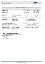
Страница 9: ...ize 1 87 mm size 2 and 3 Installation side Operating side Weight of FKA2 EU with fusible link see table Ä 10 Sizes 1 to 3 see table Ä 10 Limit switches Connecting cable length cross section 1 m 3 0 34 mm Protection level IP 66 Type of contact 1 changeover contact gold plated Maximum switching current 0 5 A Maximum switching voltage 30 V DC 250 V AC Contact resistance approx 30 mΩ Technical data FK...

Страница 10: ...11 14 13 17 15 19 17 21 23 28 26 31 28 34 30 36 33 39 35 42 38 45 40 48 43 50 B 500 10 13 12 15 14 18 16 20 18 22 25 30 27 33 30 36 33 39 35 42 36 45 40 48 43 51 46 54 550 15 19 18 22 21 26 24 28 26 32 29 35 32 38 35 41 37 44 40 47 43 51 46 54 49 57 600 16 20 19 23 22 27 25 30 28 33 31 37 34 40 37 43 40 47 43 50 46 53 49 57 52 60 650 17 21 20 25 23 28 27 32 30 35 33 39 36 42 39 46 42 49 45 53 48 5...

Страница 11: ... 350 400 450 500 550 600 650 700 750 800 900 1000 1100 1200 1300 1400 1500 Number of holes each horizontal side 0 0 1 1 1 2 2 3 3 4 4 Number of holes each vertical side 0 0 0 1 1 1 2 2 Number of holes horizontally B or vertically H but without corner holes B 400 mm and H only with corner holes Technical data FKA2 EU with fusible link Fire damper Type FKA2 EU 11 ...

Страница 12: ...ng length A Horizontally arranged spring return actuator B Vertically arranged spring return actuator Y Keep clear to provide access for operation Installation side Operating side Weight of FKA2 EU with fusible link approx 1 kg BFL and BFN see table Ä 10 Sizes 1 to 3 and arrangement of the spring return actuator A or B see table Ä 10 Technical data FKA2 EU with spring return actuator Fire damper T...

Страница 13: ...tact 2 changeover contacts Switching voltage 5 120 V DC 5 250 V AC Switching current 1 mA 3 0 5 inductive A Contact resistance 1 Ω when new IEC protection class IP protection II IP 54 Storage temperature ambient temperature 40 55 C 30 55 C Ambient humidity 95 rh no condensation Connecting cable Actuator limit switch 1 m 2 0 75 mm 1 m 6 0 75 mm free of halo gens Spring return actuator type BFL for ...

Страница 14: ...pe of contact 2 changeover contacts Switching voltage 5 120 V DC 5 250 V AC Switching current 1 mA 3 0 5 inductive A Contact resistance 1 Ω when new IEC protection class IP protection II IP 54 Storage temperature ambient temperature 40 55 C 30 55 C Ambient humidity 95 rh no condensation Connecting cable Actuator limit switch 1 m 2 0 75 mm 1 m 6 0 75 mm free of halo gens Spring return actuator type...

Страница 15: ...changeover contacts Switching voltage 5 120 V DC 5 250 V AC Switching current 1 mA 6 A Contact resistance 100 mΩ IEC protection class IP protection II IP 54 III IP 54 Storage temperature ambient temperature 40 50 C 30 50 C Ambient humidity 95 rh no condensation Connecting cable Actuator limit switch 1 m 2 0 75 mm 1 m 6 0 75 mm free of halo gens BF actuator optional weight of FKA2 EU with fusible l...

Страница 16: ...lly arranged spring return actuator B Vertically arranged spring return actuator Y Keep clear to provide access for operation Installation side Operating side Weight of FKA2 EU with fusible link approx 1 4 kg GRA and GNA see table Ä 10 Sizes 1 to 3 and arrangement of the spring return actuator A or B see table Ä 10 Technical data FKA2 EU with spring return actuator Fire damper Type FKA2 EU 16 ...

Страница 17: ...tuator type GRA for size 1 Connecting cable at the bottom Spring return actuator GNA Construction 326 1E 126 1E Supply voltage 230 V AC 50 60 Hz 24 V AC 50 60 Hz 24 48 V DC Functional range 198 264 V AC 19 2 28 8 V AC 19 2 57 6 V DC Power rating Spring winding mechanism 7 VA 4 5 W 5 VA 3 5 W Hold position 3 5 W 2 W Running time Actuator spring return 90 s 15 s Limit switch Type of contact 2 change...

Страница 18: ... 6 A inductive 2 A DC 2 A IEC protection class IP protection II IP 42 or IP 54 III IP 42 or IP 54 Storage temperature ambient temperature 20 to 50 C 20 to 50 C Ambient humidity 95 rh no condensation Connecting cable Actuator limit switch 0 9 m 6 0 75 mm free of halogens GGA actuator optional weight of FKA2 EU with fusible link approx 2 5 kg Connecting cable at the bottom FKA2 EU with Joventa sprin...

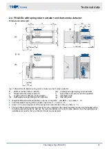
Страница 19: ...side Operating side Weight of FKA2 EU with fusible link approx 2 5 kg BFL and BFN see table Ä 10 Technical data for spring return actuator see table Ä 13 and Ä 15 Sizes 1 to 3 and arrangement of the spring return actuator A or B see table Ä 10 The type RM O 3 D duct smoke detector must be installed in the lower inspection access and arranged at the top when assembling the fire damper For technical...

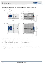
Страница 20: ...ide H L Length of the fire damper casing length Y Keep clear to provide access for operation x 75 mm size 1 87 mm size 2 and 3 Installation side Operating side Sizes 1 to 3 see table Ä 10 Note Approvals under building regulations may be required for the use of air transfer units This must be checked and applied for by others Technical data FKA2 EU with fusible link and cover grille used as an air ...

Страница 21: ...echnical data for spring return actuator see table Ä 13 and Ä 15 Sizes 1 to 3 and arrangement of the spring return actuator A or B see table Ä 10 The type RM O 3 D duct smoke detector must be installed in the lower inspection access and arranged at the top when assembling the fire damper For technical details on the duct smoke detector see the operating and installation manual for the type RM O 3 ...

Страница 22: ...ediately after arrival for transport damage and completeness In case of any damage or an incomplete shipment contact the ship ping company and your supplier immediately Fire damper Attachments accessories if any Operating manual 1 per shipment Colour hues on the damper blade The blades of fire dampers are treated with a greenish impregnating agent Resulting colour hues on the damper blade are due ...

Страница 23: ...al wool 100 EI 90 S N N 4 on installation kit WA 100 EI 90 S E 4 removed wall mounting Installation kit WE 100 EI 90 S E 4 removed wall penetration Installation kit WE 100 EI 90 S E 4 in fire batt 100 EI 120 S W W 4 100 EI 90 S W W 4 in fire batt multiple mounting 100 EI 90 S W W 4 Metal stud walls in 94 EI 120 S N N 4 94 EI 90 S N N 4 94 EI 60 S N N 4 94 EI 30 S N N 4 in combined assembly 94 EI 9...

Страница 24: ...er stud walls in 130 EI 120 S N N 4 130 EI 90 S N N 4 110 EI 60 S N N 4 105 EI 30 S N N 4 in multiple mounting 130 EI 90 S N N 4 in multiple mounting Common duct 130 EI 90 S N 4 in installation kit ES 130 EI 120 S E E 4 130 EI 90 S E E 4 110 EI 60 S E E 4 105 EI 30 S E E 4 in with mineral wool 130 EI 60 S T 4 in fire batt 130 EI 120 S W W 4 130 EI 90 S W W 4 110 EI 60 S W W 4 105 EI 30 S W W 4 in ...

Страница 25: ...90 S E 4 in with mineral wool 95 EI 60 S T 4 in fire batt 95 EI 90 S W W 4 Shaft wall with metal support structure in 90 EI 90 S N N 4 80 EI 90 S N N 4 75 EI 30 S N N 4 in combined assembly 90 EI 90 S N N 4 in installation kit ES 90 EI 90 S E 4 80 EI 90 S E 4 75 EI 90 S E 4 Shaft wall without metal support structure in installation kit ES 40 EI 90 S E 4 Solid ceiling slabs in 100 125 3 EI 120 S N ...

Страница 26: ... S W W 4 in fire batt Multiple mounting 150 EI 90 S W W 4 Solid wood ceil ings in 140 EI 90 S N N 4 in with additional cladding 112 5 EI 90 S N N 4 in installation kit ES 140 EI 90 S E 4 in installation kit ES with additional cladding 112 5 EI 90 S E 4 Wooden beam ceil ings in 167 5 EI 90 S N N 4 155 EI 60 S N N 4 142 5 EI 30 S N N 4 in installation kit ES 167 5 EI 90 S E 4 155 EI 60 S E 4 142 5 E...

Страница 27: ... mm The distance from load bearing structural ele ments is 75 mm A maximum of two fire dampers must be installed in a single installation opening Fire dampers are allowed to be in mortar based installation at a distance of 40 mm from steel beams wooden beams or wooden ceilings with fire protection claddings The fire resistant clad ding panel material must be manufactured in accordance with a natio...

Страница 28: ...elines and regulations for combustible building materials and smoke formation classes Insulation is non hazardous in terms of fire safety if the following requirements are met The insulation does not impair the function of the fire damper The fire damper remains accessible the inspection accesses and the rating plate are accessible and The insulation does not penetrate walls or ceilings Fig 10 The...

Страница 29: ... or vertical a Minimum distance between two fire dampers Unless specified otherwise in the respective installa tion description the installation is carried out in sep arate installation openings The distance between two fire dampers is 200 mm The fire damper with assembled duct smoke detector must be installed in a horizontal installation position duct smoke detector at the top deviations on reque...

Страница 30: ...ation details for fire resistance properties Supporting construction Installation type Mortar based instal lation Dry mortarless installation Fire batt installation Solid wall A F A B D F Gypsum wall boards E F Lightweight partition wall with metal support A F E F A B D F Timber stud wall half timbered construction A B D F E F A B D F Solid wood wall cross laminated timber wall E F E F E F Shaft w...

Страница 31: ...sition the fire damper in the centre of the installa tion opening then push it in so that the distance between the operating side flange and the wall ceiling is 195 mm Connect extension piece or duct if required In case of mortar based installation the open spaces between the fire damper casing and the wall or ceiling slab must be closed off with mortar Entrapped air is to be avoided The mortar be...

Страница 32: ... installation kit must be mounted on the fire damper by others Enough clear space is required for installation of the installation kit The installation kit ES is fastened with dry wall screws Æ 5 5 mm and brackets in which case the dry wall screws must always engage with the stud frame The dry wall screws must be long enough so that the damper can be firmly fastened The holes of the fixing points ...

Страница 33: ... walls and ceiling slabs Casing length L 500 mm The installation kit must be mounted on the fire damper by others Enough clear space is required to attach the instal lation kit to the wall at least 150 mm around the perimeter Cladding and wall ceiling connection must be made on 4 sides The fire damper is flanged onto a sheet steel duct shortened so as to be flush mounted in the wall ceiling The fi...

Страница 34: ...nstallation situation and the Promat manual Installation with fire batt The distance from the operating side flange to the wall or ceiling has to be 195 mm Fire batt systems consist of two layers of mineral wool slabs gross density 140 kg m Apply fire resistant sealant to the cut faces of the mineral wool slabs and fit them tightly into the instal lation opening Seal any gaps between the mineral w...

Страница 35: ...Flammotect Combi S90 Fire resistant sealant AGI Flammotect COMBI S90 Fire batt system B max mm H max mm Promat 3750 1840 Hilti 3000 2115 Hensel 1900 1400 Fire batt system B max mm H max mm SVT OBO Bettermann Würth AGI Fig 20 Fire batt installation in solid walls and ceiling slabs lightweight partition timber stud wall half tim bered construction and solid wood walls E Installation area Dimensions ...

Страница 36: ...opean classification to EN 13501 2 or equivalent national classification Cladding on both sides made of gypsum bonded or cement bonded panel materials fibre reinforced gypsum or fire rated calcium silicate boards Wall thickness W 94 mm for compartment walls or safety partition walls W 100 mm Distance between metal support structures 625 mm distance between metal support struc tures in compartment ...

Страница 37: ...30 clad ding reinforcing boards according to installation details 625 mm distance between metal studs Be sure to follow the manufacturers instructions for the height width and thickness of walls Create an installation opening with trimmers studs and noggings If necessary provide trim panels and screw fix them to the support structure Installation is carried out with the actuator on the outside of ...

Страница 38: ...al requirements solid walls Solid wall Ä 36 Distances and installation orientations see Ä 30 Installation type Installation opening mm Distance mm B1 H1 s1 s2 Mortar based installation B 450 max H 450 max 225 60 225 Dry mortarless installation with fire batt 1 H 1200 max H 1200 max 40 600 60 600 1 Observe maximum permitted size of the fire batt Installation Solid walls Fire damper Type FKA2 EU 38 ...

Страница 39: ...g 24 Mortar based installation into a solid wall flange to flange illustration shows side by side installation applies also to installation of dampers on top of each other 1 FKA2 EU 2 1 Mortar 3 1 Solid wall Up to EI 120 S Additional requirements mortar based installation into solid walls Solid wall Ä 36 Casing length L 305 or 500 mm Installation Solid walls Mortar based installation Fire damper T...

Страница 40: ...t walls with metal support struc ture Fig 25 Lightweight partition wall with metal support structure and cladding on both sides Installation Lightweight partition walls and compartment walls with metal support structure Fire damper Type FKA2 EU 40 ...

Страница 41: ... safety partition wall installation near the ceiling 4 1 Solid ceiling slab solid floor 5 1 Dry wall screw 5 6 Screw or steel rivet 6 5 Mineral wool depending on wall construction 7 1 UW section 7 2 CW section 7 3 UA section 7 10 Trim panels according to installation details 7 13 Cladding 7 23 Sheet steel insert depending on wall manu facturer if any B1 H1 Installation opening B2 H2 Opening in the...

Страница 42: ...ll screw 5 2 Hexagon head screw M6 5 5 Carriage bolt L 50 mm with washer and nut 5 6 Steel rivet 5 14 Angle bracket 7 1 UW section 7 2 CW section 7 3 UA section Installation opening according to installation details Installation Lightweight partition walls and compartment walls with metal support structure Fire damper Type FKA2 EU 42 ...

Страница 43: ...r corresponding installation details max 2 12 5 mm 1 25 mm 2 Installation opening tolerance 2 mm 3 Trim panels according to installation details required Subsequent installation Fig 28 Subsequent installation in lightweight partition wall for clear opening 475 mm between two shelves mortar based installation shown also applicable for dry mortarless installation 1 FKA2 EU 2 1 Mortar 3 2 Lightweight...

Страница 44: ...wool strips A1 filler as an alternative if required to even out an uneven wall 7 5 Steel support structure box section 7 10 Trim panels 7 13 Cladding 7 14 Reinforcing board of the same material as the wall 7 23 Sheet steel insert depending on wall manufac turer 9 2 Extension piece or duct Installation near the floor analogous to optional H1 B1 Installation opening see table Ä 43 Z For fixing see F...

Страница 45: ...or fixing see Fig 16 to Fig 18 Up to EI 60 EI 30 S Additional requirements dry mortarless installation with installation kit ES in lightweight partition walls Lightweight partition wall Ä 36 Casing length L 500 mm Distance from the fire damper to the adjacent structural elements 110 120 mm depending on the arrange ment of brackets 4 sided metal section 65 70 mm distance between the fire damper wit...

Страница 46: ...for installation near the ceiling 1 Mount the installation kit onto the fire damper 2 Insert the fire damper centred into the installation opening and fix with brackets and dry wall screws to the stud frame see Fig 16 to Fig 18 Installation Lightweight partition walls and compartment walls with metal support structure Dry mortarless installation with installation kit ES Fire damper Type FKA2 EU 46...

Страница 47: ...solid floor 6 5 Mineral wool depending on wall construction 6 11 Insulating strip depending on wall construction 7 10 Trim panels 7 11 Trim panels double layer 7 13 Cladding Installation near the floor analogous to to EI 120 S B H 200 100 800 400 mm horizontal installation position Up to EI 90 S EI 30 to EI 120 S Installation Lightweight partition walls and compartment walls with metal support str...

Страница 48: ... 6 5 Mineral wool depending on wall construction 6 11 Insulating strip depending on wall construction 7 10 Trim panels 7 11 Trim panels double layer 7 13 Cladding 7 14 Reinforcing board of the same material as the wall EI 30 S Up to EI 60 S Installation Lightweight partition walls and compartment walls with metal support structure Dry mortarless installation with fire batt Fire damper Type FKA2 EU...

Страница 49: ...n both sides 6 5 Mineral wool depending on wall construction 7 10 Trim panels 7 13 Cladding 7 23 Sheet steel insert depending on wall manufac turer Up to EI 90 S Additional requirements dry mortarless installation into lightweight partition walls with fire batt Lightweight partition wall Ä 36 Casing length L 305 or 500 mm Fire batt systems installation details distances dimensions see Ä 34 f Suspe...

Страница 50: ... insulation according to Promat work sheet 478 for example Load the sus pension system only with the weight of the fire damper ducting must be suspended separately For weights kg of FKA2 EU fire dampers see Ä 10 In addition to the fixing systems described in this manual you may also use fixing systems that have been approved by accredited testing institutes This applies in particular to the fire d...

Страница 51: ...nsion system according to Promat manual construction 478 latest edition 9 5 Suspension system by others consisting of a Threaded rod M10 B H 800 200 mm M12 B H 1000 600 mm M12 B H 1000 600 mm b Hilti mounting rail MQ 41 3 mm or equivalent c Hilti drilled plate MQZ L13 or equivalent days Hexagon nut with washer Damper sizes 1000 600 mm require two sus pension points underneath the fire damper at a ...

Страница 52: ...d M12 with washer and nut 5 18 Steel angle section to EN 10056 1 L 40 mm 40 mm 5 mm galvanised or painted or equivalent 9 1 Flexible connector recommended Note Each fire damper has to be suspended both on the operating side and on the installation side The suspension is carried out in each case above or below the flange Installation Fixing the fire damper Fixing the damper when a fire batt is used...

Страница 53: ...stem 4 1 Solid ceiling slab 5 2 Hexagon head screw M12 with washer and nut 5 9 Steel angle 40 40 5 mm 5 17 Anchor bolt or equivalent for attachment to the ceiling slab 11 4 Underlay material non combustible to be pro vided by others Installation Fixing the fire damper Fixing the damper when a fire batt is used Fire damper Type FKA2 EU 53 ...

Страница 54: ... 1 Solid ceiling slab 5 2 Hexagon head screw M12 with washer and nut 5 9 Steel angle 40 40 5 mm 5 17 Anchor bolt or equivalent for attachment to the ceiling slab 11 4 Underlay material non combustible to be pro vided by others Installation Fixing the fire damper Fixing the damper when a fire batt is used Fire damper Type FKA2 EU 54 ...

Страница 55: ...others 2 Optional release mechanism e g TROX duct smoke detector Type RM O 3 D or RM O VS D 3 Indicator light for CLOSED position to be provided by others 4 Indicator light for OPEN position to be provided by others The fire damper may be equipped with a spring return actuator for a supply voltage of 230 V AC or 24 V AC DC See the performance data on the actuator rating plate The spring return act...

Страница 56: ...on of the damper blade 1 2 is indicated by the position of the handle 1 6 Fig 41 damper blade position indicator 1 Damper blade 1 2 is closed 2 Damper blade 1 2 is open Close the damper blade Fig 42 Close the damper blade Requirement Fire damper is open 1 Pull the knob of the thermal release mechanism 10 14 forwards in the direction of the arrow to release 2 the handle 1 6 3 The handle 1 6 swivels...

Страница 57: ... 3 The damper blade 1 2 is open and 4 the handle 1 6 indicates that the damper blade 1 2 is open 6 1 2 Fusible link size 2 and 3 damper blade position indicator The position of the damper blade 1 2 is indicated by the red arrow on the cover of the handle 1 6 Fig 44 damper blade position indicator 1 Damper blade 1 2 is closed 2 Damper blade 1 2 is open Functional test Fire damper with fusible link ...

Страница 58: ...he fusible link holder rocker 10 16 3 The handle 1 6 swivels automatically in the direction of the arrow clockwise 4 and clicks into the CLOSED position on the inter lock 1 7 5 The damper blade 1 2 is closed and 6 the red arrow on the cover of the handle 1 6 indi cates that the damper blade 1 2 is closed Functional test Fire damper with fusible link Fusible link size 2 and 3 Fire damper Type FKA2 ...

Страница 59: ...n the handle 1 6 in the direction of the arrow counter clockwise and do not lift it any more 4 The handle 1 6 clicks into the OPEN position in the opening of the fusible link holder rocker 10 16 5 The damper blade 1 2 is open and 6 the red arrow on the cover of the handle 1 6 indi cates that the damper blade 1 2 is open Functional test Fire damper with fusible link Fusible link size 2 and 3 Fire d...

Страница 60: ...ed 2 Damper blade is open Closing opening the damper blade with spring return actuator Fig 49 Functional test FKA2 EU with BFN actuator shown in OPEN position CAUTION Danger of injury when reaching into the fire damper while the damper blade is moving Do not reach into the fire damper while actuating the release mecha nism Requirement Power is being supplied 1 Push the push button 1 and keep it pu...

Страница 61: ... the spring winding mechanism 2 Turn the crank handle in the direction of the arrow 2 to just short of the travel stop and hold it 3 Set the interlock 3 to Lock closed ð The damper blade remains in the OPEN posi tion 4 Remove the crank handle Close the fire damper Fig 51 Functional test without power supply CAUTION Danger of injury when reaching into the fire damper while the damper blade is movin...

Страница 62: ...the test results TROXNETCOM systems such as TNC EASYCON TROL or AS interface meet all these requirements For more informationen see www troxtechnik com TROXNETCOM systems allow for automatic functional tests they do not replace maintenance and cleaning which have to be carried out in regular intervals or depending on the condition of the product The docu mentation of test results makes trends visi...

Страница 63: ...ough the ventilation system If the temperature in the duct 72 C 95 C in warm air ventilation systems or the ambient temperature 72 C rises in the event of a fire the thermal release mechanism is triggered This action closes the damper blade CLOSED fire dampers Fire dampers which close while the ventilation and air conditioning system is running must be inspected before they are opened again in ord...

Страница 64: ...tructure and cladding on both sides 40 Lightweight partition walls with timber support structure 37 Limitation of liability 3 Limit switch 55 M Metal stud walls 23 Mortar based installation 23 Multiple mounting 23 O Operating side 9 12 16 20 Operation 63 P Packaging 22 Partial mortaring 23 Personnel 6 Product sticker 8 S Service 3 Shaft walls 23 Shaft walls with metal support structure 37 Shaft wa...

Отзывы: