background image

28.09.2017

WidowX Robot Arm Assembly Guide

http://www.trossenrobotics.com/productdocs/assemblyguides/widowx-robot-arm-mk2.html

13/24


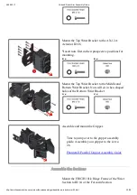
Mount the MX-28T Actuator with ID #1 to the top
side of the Middle Base. 
 
*
Insert nuts first in their respective positions for
mounting.

8 x

8 x


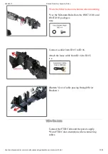
Mount the ArbotiX Board to the standoffs on the
bottom side of the Middle Base. 
 
*
Note the ArbotiX orientation when mounting.
Ensure Barrel Jack is facing towards the rear of the
base.

4 x


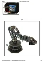
Connect a 200mm cable from the left side of ID #1
to the ArbotiX Board, through the cut out on the
Middle Base.

1 x


(Bottom View of cable connection to the ArbotiX
Board)

Содержание WidowX MKII

Страница 1: ...botics com productdocs assemblyguides widowx robot arm mk2 html 1 24 WidowX MKII Robot Arm Guide Version This Guide is for the WidowX Robot Arm MK II The assembly guide for the original WidowX Robot A...

Страница 2: ...Included Small Flat Head Screw Driver Parts List Note Some of the parts in some assemblies come packaged in separate smaller bags because they come with a bracket or other various parts Please review...

Страница 3: ...28 09 2017 WidowX Robot Arm Assembly Guide http www trossenrobotics com productdocs assemblyguides widowx robot arm mk2 html 3 24 1 X 1 X 1 X 1 X 1 X 1 X 1 X 1 X 1 X 2 X 2 X 1 X...

Страница 4: ...28 09 2017 WidowX Robot Arm Assembly Guide http www trossenrobotics com productdocs assemblyguides widowx robot arm mk2 html 4 24 1 X 1 X 2 X 1 X 1 X 1 X 1 X 1 X 1 X 2 X...

Страница 5: ...wX Robot Arm Assembly Guide http www trossenrobotics com productdocs assemblyguides widowx robot arm mk2 html 5 24 10 X 8 X 22 X 10 X 14 X 32 X 8 X 4 X 10 X 16 X 24 X 18 X 40 X 12 X 6 X 1 X 4 X 9 X 8...

Страница 6: ...es Peel the masking paper off before getting started There also may be some dust on your parts This is from the laser cutting manufacturing process It is harmless and can be cleaned up by wiping with...

Страница 7: ...o Lock Horn Installation Mount one each of the HN05 N102 Servo Horn to the two MX 64 servos using a Hex Socket Head M3 x 8mm bolt There is a notch on the spline indicating the position of the servo Ma...

Страница 8: ...spline indicating the position of the servo Make sure this is facing up centered position and that the single dot on the horn is aligned with the notch as shown NOTE there is a plastic washer that you...

Страница 9: ...mbly You will need to ID your servos before building If you have not done so yet go to the DynaManager Guide and ID your servos You will need to ID each one of your servos with the appropriate ID show...

Страница 10: ...28 09 2017 WidowX Robot Arm Assembly Guide http www trossenrobotics com productdocs assemblyguides widowx robot arm mk2 html 10 24...

Страница 11: ...widowx robot arm mk2 html 11 24 Pre Step Sand your Gripper Rails AX Parallel Gripper Fine Tuning For proper functionality of your gripper please pay attention to this guide The gripper rails are desig...

Страница 12: ...s assemblyguides widowx robot arm mk2 html 12 24 Build the Base Mount Standoffs to the bottom side of the Middle Base 8 x 8 x Mount Standoffs for the ArbotiX Board to the bottom side of the Middle Bas...

Страница 13: ...uts first in their respective positions for mounting 8 x 8 x Mount the ArbotiX Board to the standoffs on the bottom side of the Middle Base Note the ArbotiX orientation when mounting Ensure Barrel Jac...

Страница 14: ...robot arm mk2 html 14 24 Mount the Bottom Base to the standoffs on the bottom side of the Middle Base 8 x Apply the Rubber Feet to the bottom side of the Bottom Base 8 x Pay close attention to the or...

Страница 15: ...Pan Plate to the inside ring of the Bearing Note the Pan Plate orientation when mounting 6 x 6 x Mount the FR05 H101 Hinge Frame to the top side of the Pan Plate Mounting holes on the frame are tappe...

Страница 16: ...g and into the standoff assemblies from the Middle Base Note the Pan Cover orientation when mounting 6 x Build the Arm Mount the MX 64T Actuator ID 2 to the Hinge Frame Note the ID 2 orientation when...

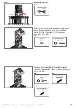
Страница 17: ...bot arm mk2 html 17 24 1 x Insert the M2 5 nuts in the appropriate sockets and mount the two Shoulder Plates to the Shoulder Servo ID 2 Elbow Servo ID 3 as shown Repeat for other side 16x 16 x Combine...

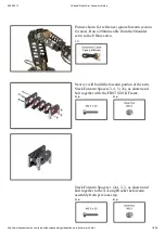
Страница 18: ...gnore forearm section for now Run a 200mm cable from the Shoulder servo to the Elbow servo 1x Next we will build the forearm portion of the arm Stack Forearm Spacers 3 4 5 2x as shown and bolt togethe...

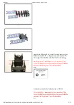
Страница 19: ...shown You will use the 2x clear spacers included with the bracket assembly Note the ID 3 orientation when mounting The servo should be centered and the forearm should be mounted at 90 degrees from th...

Страница 20: ...l 20 24 Seat 4x M2 5 nuts in the bottom sockets of the ID 4 servo and attach it to the FR07 S101K Frame as shown 4 x 4 x Connect the cable coming from Servo ID 3 to Servo ID 4 Picture shown for refere...

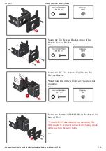
Страница 21: ...top of the Bottom Reverse Bracket 2 x 2 x Mount the AX 12A Actuator ID 5 to the Top Reverse Bracket Insert nuts first in their prospective positions for mounting 6 x 6 x Mount the Bottom and Middle W...

Страница 22: ...itions for mounting 8 x 8 x Mount the Top Wrist Bracket to the Middle and Bottom Wrist Bracket Nuts will sit in hex shaped holes of the Bottom Wrist Bracket 4 x 4 x Assemble and mount the Gripper Time...

Страница 23: ...t Section orientation when mounting Use the M2x4mm Bolts from the HN07 N101 and HN07 I101 packages 10 x Connect a cable from ID 5 to ID 6 Attach the loose cable from ID 4 to ID 5 1 x Bottom View of ca...

Страница 24: ...28 09 2017 WidowX Robot Arm Assembly Guide http www trossenrobotics com productdocs assemblyguides widowx robot arm mk2 html 24 24 Fin...

Отзывы: