manualshive.com logo in svg
background image


1740 Eber Rd 

Tronair, Inc.


Phone: (419) 866-6301 

Holland, OH 43528-9794 

www.tronair.com


800-426-6301 

USA 

Email: [email protected]


Fax: (419) 867-0634 


Operation & Service Instructions 


Model:  5731 

Hydraulic Power Unit 


08/2016 

 Rev. 08 


Содержание 5731

Страница 1: ...Rd Tronair Inc Phone 419 866 6301 Holland OH 43528 9794 www tronair com 800 426 6301 USA Email sales tronair com Fax 419 867 0634 Operation Service Instructions Model 5731 Hydraulic Power Unit 08 201...

Страница 2: ...Modified 12 2 1 Self Calibration 05 10 2009 Modified 9 10 Electrical Components Added 9 10 1 Electrical Components With 100 ft Input Cord Option 06 06 2010 Modified illustration for 5 3 5 Hydraulic P...

Страница 3: ...ol Panel 6 5 3 3 Hydraulic Control Panel 7 5 3 4 Rear Panel Controls 8 5 3 5 Hydraulic Pump Controls 9 5 3 6 Hand Pump Controls Option M 10 5 3 7 Dual System Controls Option C 11 5 4 START UP PROCEDUR...

Страница 4: ...alve 34 9 7 3 c Bypass Valve 34 9 8 RESERVOIR ASSEMBLY 35 9 9 RETURN MANIFOLD ASSEMBLY 37 9 9 1 Return System Pressure Relief Valve 38 9 10 ELECTRICAL COMPONENTS 39 9 10 1 Electrical Components With 1...

Страница 5: ...el 5731 Hydraulic Power Unit 08 2016 Rev 08 12 4 ANALOG TEMPERATURE GAUGE Pyrometer 59 12 4 1 Self Calibration 59 13 0 IN SERVICE SUPPORT 60 14 0 GUARANTEES LIMITATION OF LIABILITY 60 15 0 APPENDICES...

Страница 6: ...supply and protection equipment in the facility 2 0 SAFETY INFORMATION 2 1 USAGE AND SAFETY INFORMATION The HPU provides pressurized hydraulic fluid for performing aircraft maintenance To insure safe...

Страница 7: ...mark but below the maximum fluid level See Figure 5 3 1 Front Panel Controls for reservoir fill location 3 3 CONNECTING ELECTRICAL LEADS Electrical Shock Never touch electrical wires or components whi...

Страница 8: ...in 25 4 mm Working Diameter Return Hoses 25 ft 7 62 m Standard Length 50 ft 15 24 m Optional Length 24 1 in 38 1 mm Working Diameter Hand Pump Hose 15 ft 4 57 m Standard Length 6 3 8 in 9 53 mm Worki...

Страница 9: ...nt Hand Pump Option M 2 micron rating non bypass microglass type Non cleanable element Air Desiccant 3 micron filter silica gel desiccant type Non cleanable element 5 2 6 Hand Pump Option M Two stage...

Страница 10: ...lic Pump Controls Reservoir Selector For selecting between using the aircraft reservoir or the HPU reservoir Sight Gauge Visual indicator displays the fluid level in the reservoir Reservoir Fill Acces...

Страница 11: ...ervoir is above the normal Indicator Light Option L operating range The HPU will shut down until the fluid level is restored to a normal operating level Low Reservoir Fluid Level Light is illuminated...

Страница 12: ...perature Pressure Gauge Calibration Port Allows for calibration of the system pressure gauge up to the operating pressure of HPU Calibration port shut off valve must be used in conjunction with the ca...

Страница 13: ...rs the fluid returning from the aircraft before it enters the HPU Pressurized Fluid Sample Port A sample valve is provided to obtain a fluid sample for analysis In order to obtain a representative sam...

Страница 14: ...ls The hydraulic pump flow control and pressure control are located through the pump control access door FIGURE 5 3 5 Hydraulic Pump Controls Flow Control This control is used to set the maximum flow...

Страница 15: ...and closing the hand pump relief screw and stroking the hand pump arm Hand Pump Relief Screw Accessed through the front panel opening this screw allows opening and closing of the hand pump hydraulic...

Страница 16: ...artially open position Fluid Pressure Hose Connects HPU to aircraft pressure systems Fluid Return Hose Connects HPU to aircraft return systems WARNING NEVER open or close dual system valves without sh...

Страница 17: ...st be prepared per section 3 0 Preparation Prior to First Use and section 5 4 1 First Time or Different Electrical Supply ONLY before starting the HPU b Operator must be familiar with this manual and...

Страница 18: ...rease the flow control setting until the cavitation is eliminated b HPU Reservoir Position Open Loop In this position the HPU reservoir supplies fluid to the pump and accepts return fluid from the air...

Страница 19: ...he pump output will be divided between the two systems Also cross flow between aircraft reservoirs may occur if a reservoir level or pressure differential exists Select valve positions prior to starti...

Страница 20: ...1 2 Voltage Phase Monitor Indicator Options H J The indicator light for the voltage phase monitor is an active light which will illuminate if there is a problem with the incoming electrical power sour...

Страница 21: ...ng material for cushioning or suspension is required 6 4 LABELING OF PACKAGING Packaging should be labeled as follows DO NOT DROP THIS SIDE UP DO NOT STACK 6 5 STORAGE COMPATIBILITY No special conside...

Страница 22: ...l overload device motor starter will reset automatically after sufficient cooling The tripped condition is usually caused by loading the motor beyond its rated capacity however any condition such as u...

Страница 23: ...phase legs Pump inlet is not receiving enough fluid Follow the procedure for Air in pump inlet lines in Section 8 2 cavitation Flow path is open Pressure is resistance to flow The HPU will reach full...

Страница 24: ...Periodic greasing is necessary on a frequently used HPU Reference Appendix Lincoln Motor Manual for details FIGURE 9 2 Electric Motor Hydraulic Pump Assembly PARTS LIST Item Part Number Description Qt...

Страница 25: ...3 1 Hydraulic Pump PARTS LIST Fluid Type Aviation Phosphate Ester Type IV Item Part Number Description Qty 1 N 2001 24 S E Elbow 12 16 1 2 N 2078 11 Flange 90 Elbow 1 3 N 2679 12 Elbow Flange 1 4 N 20...

Страница 26: ...r is noticed with the hydraulic fluid a sample analysis should be performed to determine the condition of the fluid See Section 5 9 Sample Valve Operation Refer to the manufacturer of the specific flu...

Страница 27: ...ndard filter changes depend on how frequently the HPU is used and the cleanliness of the fluid along with the environment to which the HPU is exposed Periodic fluid analysis is recommended to properly...

Страница 28: ...nt Replace the return filter element at the same time the pressure filter element is being replaced PARTS LIST Fluid Type Aviation Phosphate Ester Type IV Item Part Number Description Qty 1 HC 2006 35...

Страница 29: ...he environment to which the HPU is exposed Changing the hand pump filter element at the same time as the pressure filter element will ensure a regular maintenance schedule PARTS LIST Fluid Type Aviati...

Страница 30: ...9 5 4 Desiccant Air Filter Replace the desiccant air filter whenever the material inside the element is pink or reddish in color see Element Label for details PARTS LIST Item Part Number Description...

Страница 31: ...the flow rate is reduced to 10 gpm PARTS LIST Fluid Type Aviation Phosphate Ester Type IV Item Part Number Description Qty 1 EC 1778 DIN Connector Cable 1 2 G 1151 109224 Screw Socket Head Cap 13 1 3...

Страница 32: ...inued 9 5 6 Return Filter Assembly PARTS LIST Fluid Type Aviation Phosphate Ester Type IV Item Part Number Description Qty 1 N 2036 13 S E Fitting 37 Swivel 1 2 HC 2045 02 Filter Return 1 3 N 2007 31...

Страница 33: ...Phosphate Ester Type IV hoses as long as the fluid does not form into drops FIGURE 9 6 Hydraulic Hoses PARTS LIST Fluid Type Aviation Phosphate Ester Type IV Item Part Number Description Qty 1 TF 1040...

Страница 34: ...Item 3 Hose Assembly PARTS LIST Fluid Type Aviation Phosphate Ester Type IV Item Part Number Description Qty 1 See Page 30 Electric Panel 1 2 N 2665 08 S E Fitting ORFS Tube End 1 3 N 2634 05 S E Elbo...

Страница 35: ...on EC 1951 MN5Y Power Module w Latch 1 7 Option EC 1945 04 Light Diffused Pilot 2 8 Option EC 1951 MN5B Power Module w Latch 2 9 Option EC 1952 Push Button Illuminated Flush 1 10 Option EC 1944 Power...

Страница 36: ...Type IV Item Part Number Description Qty 1 HC 2144 Gauge Pressure 1 2 HC 1900 02 Valve Needle 1 3 HC 1122 Kit Panel Mounting 1 4 N 2008 03 S Cap JIC 1 5 N 2022 03 S Elbow Bulkhead Union 4 1 6 G 1250...

Страница 37: ...Plug O ring Hex Head 2 2 N 2042 16 S E Connector 45 Straight Thread 1 3 HC 1445 Valve Pressure Relief 1 4 J 3245 Manifold Pressure 1 5 N 2463 36 S E Fitting Reducer Expander 1 6 N 2001 03 S E Connect...

Страница 38: ...a partially open condition If service is required the new or repaired relief valve must be reset to 3 750 psig PARTS LIST Fluid Type Aviation Phosphate Ester Type IV Item Part Number Description Qty...

Страница 39: ...3 1 3 HC 2006 115 O ring Series 2 1 4 HC 2020 115 Backup Ring 1 Item 1 consists of Items 2 4 9 7 3 c Bypass Valve The Bypass Valve does not require regular general maintenance PARTS LIST Fluid Type A...

Страница 40: ...e the element is pink or reddish in color See Element label for details The Reservoir Assembly does not require regular general maintenance If periodic inspections for silt are desired be certain to t...

Страница 41: ...11 S E Connector Straight Thread 8 SAE x 8 JIC 1 9 HC 1761 Valve Ball SAE 8 Lockable 1 10 HC 2013 908 O ring Series 3 1 11 Z 2199 Weldment Clamp 2 12 HC 1542 Strainer Nipple Style 1 13 N 2007 31 S E...

Страница 42: ...Elbow Straight Thread 24 SAE x 24 JIC 1 2 N 2463 28 S E Fitting Reducer Expander 24 32 SAE 1 3 HC 2058 02 Valve Ball 1 4 N 2666 08 S E Elbow Straight Thread 24 SAE 1 5 N 2053 08 S E Plug Hex Head 12 O...

Страница 43: ...If the relief valve is serviced by the end user the valve must be set to crack at 150 7 psig before being re installed on the HPU PARTS LIST Fluid Type Aviation Phosphate Ester Type IV Item Part Numbe...

Страница 44: ...Rail Din 1 2 G 1159 103504 Screw RD HD CRS REC 10 32 x Long 12 3 G 1250 1030N Flatwasher 10 Narrow 16 4 EC 1920 Relay Overload 1 6 EC 1924 02 Lug Set Terminal 2 7 EC 1541 01 Fuse Holder IEC Class CC...

Страница 45: ...eld Current Adjustment 1 9 10 ELECTRICAL COMPONENTS continued PARTS LIST Item 60 Hz Applications Description Qty 380 460 575 5 EC 1923 EC 1922 EC 1922 Contactor IEC Motor 1 11 J 3492 J 3492 EC 1585 06...

Страница 46: ...d option Regularly inspect the external power cord for nicks cuts abrasion and fluid damage Replace power cord if damage is found See Section 10 0 Provision of Spares for recommended spare fuses FIGUR...

Страница 47: ...1 16 EC 1600 EC 1600 EC 1600 Rail Din 1 17 EC 1959 EC 1959 EC 1959 Anchor IEC End 7 18 EC 1958 EC 1958 EC 1958 Block IEC Ground 5 19 EC 1960 01 EC 1960 01 EC 1960 01 Barrier End 3 20 EC 1596 01 EC 159...

Страница 48: ...02 EC 1532 02 Lug Ground 1 16 EC 1600 EC 1600 EC 1600 Rail Din 1 17 EC 1959 EC 1959 EC 1959 Anchor IEC End 7 18 EC 1958 EC 1958 EC 1958 Block IEC Ground 5 19 EC 1960 01 EC 1960 01 EC 1960 01 Barrier...

Страница 49: ...ster Type IV Item Part Number Description Qty 1 Reference Table below Heat Exchanger 1 2 N 2007 27 S E Connector 20 SAE x 16 JIC 1 3 N 2066 20 S E Plug O ring 20 1 4 J 3404 01 Strap 2 Voltage Frequenc...

Страница 50: ...1 S 1763 01 Top Panel 1 2 Z 5549 01 Hanger 3 3 Z 5362 01 Right Side Panel 1 4 S 1782 01 Panel End 1 5 U 1099 Rigid Caster 2 6 U 1100 Swivel Caster 2 7 Z 5408 01 Front Panel 1 8 Z 4781 Filler Door 1 9...

Страница 51: ...4 1 per Option 9 13 2 Dual System Option C Refer to Section 9 6 Hydraulic Hoses concerning hose inspection PARTS LIST Fluid Type Aviation Phosphate Ester Type IV Item Part Number Description Qty 1 TF...

Страница 52: ...ommended spare fuses NOTE Wire per Electrical Schematic INS 1608 Reference Wiring Diagram INS 1597 Reference Section 9 7 1 Electrical Panel for Panel Light PARTS LIST Item Part Number Description Qty...

Страница 53: ...eral maintenance Panel indicator lights will indicate low or high fluid level NOTE Wire per Electrical Schematic INS 1608 Reference Wiring Diagram INS 1597 Reference 9 7 1 Electrical Panel for Panel L...

Страница 54: ...te Ester Type IV Item Part Number Description Qty 1 H 1009 01 Pump Handle 1 2 HC 1779 Hand Pump Two Stage 1 3 N 2001 11 S E Elbow 8 SAE x 8 JIC Flare 1 4 TF 1040 15 56 5 Hose Assembly 4 1 5 TF 1040 15...

Страница 55: ...Model 5731 Hydraulic Power Unit 08 2016 Rev 08 Page 50 This page left blank intentionally...

Страница 56: ...Model 5731 Hydraulic Power Unit 08 2016 Rev 08 Page 51 9 13 5 Hand Pump Option M continued 9 13 5 a Two Stage Pump with Relief FIGURE 9 13 5 a Two Stage Pump with Relief...

Страница 57: ...1223 Grip Handle 1 37 H 1009 01 Handle with Grip 1 HK 1095 Kit Internal Parts consists of 6 Not Shown Ball Release 0 8 Spring Outlet Check 1 9 Ball Check 4 14 Spring Bypass 1 17 Ball Bypass 1 34 Spri...

Страница 58: ...13 ADDITIONAL FEATURES continued 9 13 6 Hand Pump High Displacement Option 7 Refer to Section 9 6 Hydraulic Hoses concerning hose inspection for general maintenance on Items 3 4 11 18 and 23 hose ass...

Страница 59: ...EE MALE 6 1 11 TF 1041 02 15 ASSEMBLY HOSE 2 12 N 2001 08 S E ELBOW STR THD 6 1 13 HC 2534 SPACER BLOCK 1 14 N 2005 14 S ELBOW CONNECTOR 1 15 N 2055 04 REDUCER 8 6 1 16 N 2016 05 S TEE RUN SWIVEL NUT...

Страница 60: ...10 mph 7 24 bar at 16 kph PARTS LIST Item Part Number Description Qty 1 59 3502 Assembly Drawbar 1 2 4700 4 Lockwasher 3 8 20 3 4601 47 Nut Hex Head 3 8 24 22 4 6 1395 Assembly Front Axle 1 5 4800 3...

Страница 61: ...FT CLEAR 2 V 1914 Reservoir Selector Valve 1 V 1918 PE 1 V 1919 OPERATING INSTRUCTIONS 1 V 2008 FLOW INCREASE 1 V 2009 PRESSURE INCREASE 1 9 14 2 Fluid Labels Fluid Type Aviation Phosphate Ester Type...

Страница 62: ...umber Description Qty HC 1763 Desiccant Filter Element 1 Kit Gaskets and O rings for Main Pump 1 K 3614 Kit Pressure Filter Element 1 K 3616 Kit Return Filter Element 1 Kit Shaft Seal and Retainer for...

Страница 63: ...se the calibration port Shut off Valve on the instrument panel of the HPU Attach the Master calibration gauge to the Calibration Port on the instrument panel Set up the HPU as follows Reservoir Select...

Страница 64: ...nd can be accessed by removal of the HPU top panel See Section 9 7 2 Pyrometer for location Follow the necessary steps below 1 Remove the pyrometer bulb from the return manifold by removing the slotte...

Страница 65: ...tem will result in a service fee A decision on the extent of warranty coverage on returned products is reserved pending inspection at Tronair Any shipments to Tronair must be shipped freight prepaid F...

Страница 66: ......

Страница 67: ...APPENDIX I Declaration Of Conformity...

Страница 68: ......

Страница 69: ...accordance with European Community guidelines Mobile Hydraulic Power Unit Electric Motor Driven Relevant draft complied with by the machinery prEN 1915 1 1995 Relevant standards complied with by the...

Страница 70: ......

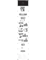
Страница 71: ...APPENDIX II Hydraulic Schematic INS 1660...

Страница 72: ......

Страница 73: ...APPENDIX III Electrical Schematic INS 1608 INS 2016...

Страница 74: ......

Страница 75: ...APPENDIX IV Wiring Diagram INS 1597 INS 2046...

Страница 76: ......

Страница 77: ...APPENDIX IV Lincoln Motor Manual...

Страница 78: ......

Страница 79: ......

Страница 80: ......

Страница 81: ......

Страница 82: ......

Страница 83: ...APPENDIX V Oilgear Pump Manual...

Страница 84: ......

Страница 85: ......

Страница 86: ......

Страница 87: ......

Страница 88: ......

Страница 89: ......

Страница 90: ......

Страница 91: ......

Страница 92: ......

Страница 93: ......

Страница 94: ......

Страница 95: ......

Страница 96: ......

Страница 97: ......

Страница 98: ......

Страница 99: ......

Страница 100: ......

Страница 101: ...APPENDIX VI Material Safety Data Sheet MSDS Hydraulic Fluid...

Страница 102: ......

Страница 103: ......

Страница 104: ......

Страница 105: ......

Страница 106: ......

Страница 107: ......

Страница 108: ......

Страница 109: ......

Страница 110: ......

Страница 111: ...APPENDIX VII ANSI B93 19M 1972 R1993 Excerpt...

Страница 112: ......

Страница 113: ......

Страница 114: ......

Страница 115: ......

Страница 116: ......

Страница 117: ...APPENDIX VIII Instrument Certification Notice...

Страница 118: ......

Страница 119: ...ed to perform the calibration check The due date for re calibration of the instrument should be based upon the date the instrument was placed in service in your facility Re calibration should be done...

Отзывы: