


Installation
Intelligent Gyro Compass (iGC)
0707-SOM-00004-7
16
© Tritech International Ltd.
1. The connector should not be exposed to long-term heat or sunshine. If this occurs, and
the connectors are very dry, soak in fresh water before use
2. Ensure the connectors are lubricated - the recommended lubricant is Molykote 44 Medium
-but use sparingly. Half a match head dose per contact is adequate.
3. Any accumulation of sand or mud in the female contact should be removed with fresh
water. Failure to do so could result in the splaying of the female contact and damage to
the O-ring seals.
4. Do not overtighten the bulkhead nuts
5. Do not disconnect by pulling on the cable and avoid sharp bends at cable entry
6. When using bulkhead connectors see that there are no angular loads as this destroys the
connector
7. When disconnecting, pull straight, not at an angle. Ensure the above points are fulfilled
to get the best out of your connectors. If in doubt, please contact your local distributor or
MacArtney A/S for advice.
The mated connector should be retained using the Delrin locking sleeve supplied with
the iGC. This ensures that the connector does not become inadvertently partially or fully
disconnected.
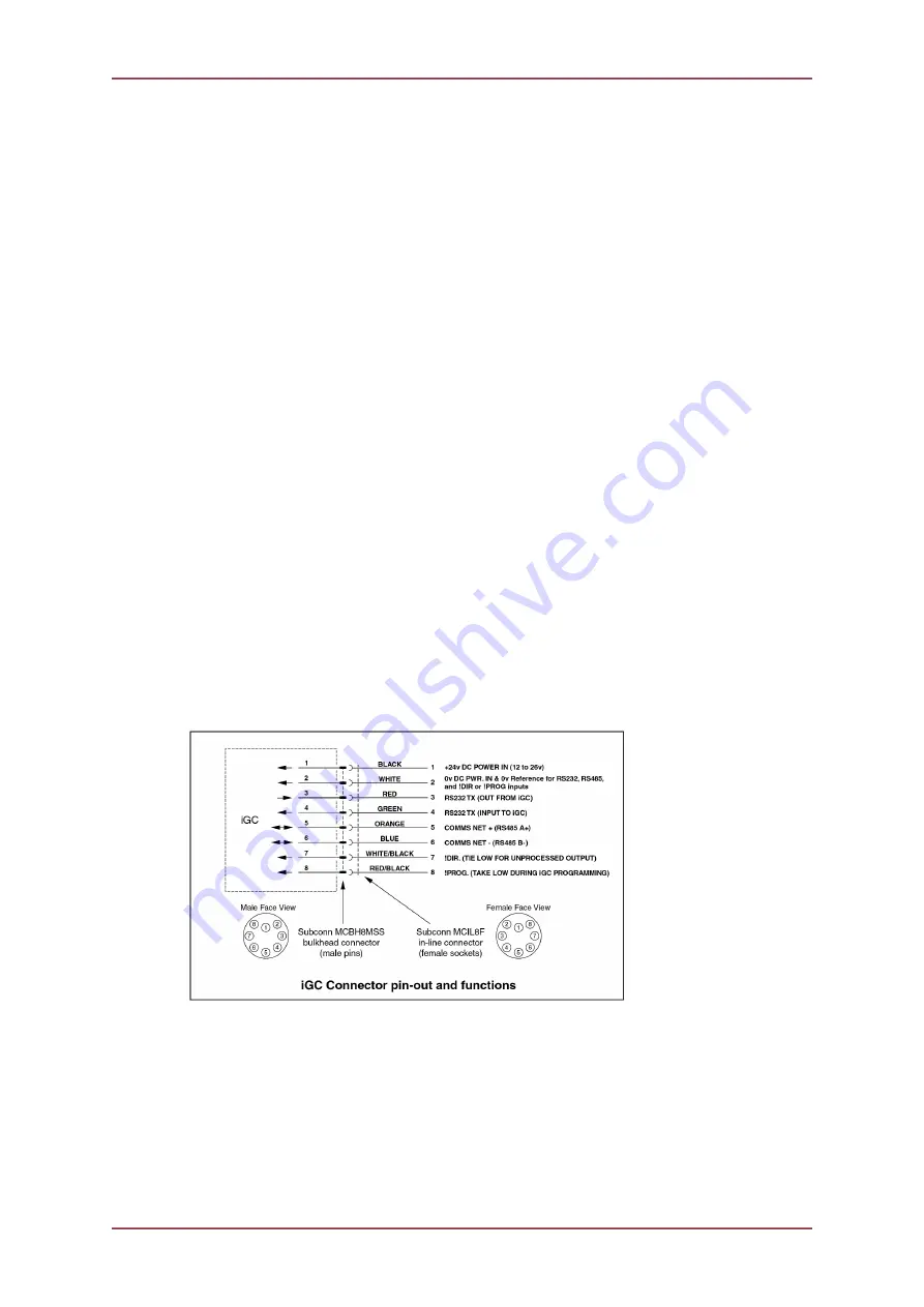
The iGC requires electric power at 24v DC nominal supply, operating current typically
between 220mA and 250mA. The iGC will however function correctly at any voltage in the
range 12v DC to 26v DC.
The power supply should be from a regulated and smooth (low ripple) power supply for best
results. An unregulated or un-smoothed supply should not be used.
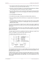
The following drawing details the pin-outs of the iGC:
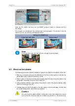
If the operating mode that the iGC is to be used in differs from the mode settings as the unit
was supplied, the iGC will need to be opened and the Mode Switch settings adjusted. This
is covered in section 7.4.2 below.
If RS485 telemetry is going to be used, check that the selector jumpers JP1, JP2 and JP3
are in their correct positions as the unit was supplied. If not, the iGC will need to be opened
and the Jumper settings adjusted as described below. The correct settings are given in the
following table:
Содержание iGC
Страница 12: ...Typical Applications Intelligent Gyro Compass iGC 0707 SOM 00004 7 12 Tritech International Ltd ...
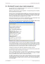
Страница 30: ...Operation Intelligent Gyro Compass iGC 0707 SOM 00004 7 30 Tritech International Ltd Typical screenshot ...
Страница 39: ...Intelligent Gyro Compass iGC 0707 SOM 00004 7 39 Tritech International Ltd Appendix B General Assembly Drawing ...
Страница 51: ...Appendix G iGC iFG Electrical Interconnection Schematic ...


