background image

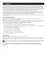
6

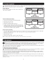
8. System Operation

9. Maintenance

Do not operate the “SW2” switch unless the UPS is in BYPASS mode! Failure to follow the operating instructions for this equipment 

could result in equipment damage, fire, severe injury or death!

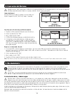
ON

OFF

ON

OFF

OFF

ON

ON

OFF

ON

OFF

OFF

ON

Normal Operation

The “SW1” Switch is Closed/On. The “SW2” Switch is Open/Off. The 

“SW3” Switch is Closed/On.

Transfer to Maintenance Bypass

1.  Transfer the UPS to the Bypass mode before proceeding.
2.  Close/turn on the “SW2” switch.
3.  Open/turn off the “SW3” switch.
4.  The UPS is now ready for routine maintenance.
5.  If further maintenance requires a total shutdown of the UPS and 

isolation from the input, the “SW1” switch must be opened/turned 
off and the battery supply to the UPS must be disconnected. Refer 
to your UPS manual for proper shutdown procedures.

Return to Normal Operation

1.  If the “SW1” switch was opened/turned off for maintenance, then follow the UPS manual for proper startup procedures. To restore input 

power to the UPS, close/turn on the “SW1” switch. Make sure the UPS is in Bypass mode before proceeding.

2.  Close/turn on the “SW3” switch.
3.  Open/turn off “SW2” switch.
4.  Transfer the UPS from Bypass mode to Line mode (Online mode).

Note:

 To use Bypass position contacts, refer to your UPS system’s owner’s manual for connection instructions.

SW1

SW1

SW2

SW2

POSITION 1 

(NORMAL OPERATION)

POSITION 1 

(IN EXTERNAL BYPASS)

SW3

SW3

Before installing or maintaining this equipment, it is extremely important to read this manual and be sure that all equipment drawings 
and schematics are reviewed and clearly understood. If there are any questions concerning this manual or any of the installation or 

maintenance procedures and/or requirements, please contact a Tripp Lite representative before proceeding.
Inspection and maintenance should only be performed on equipment that has been de-energized and electrically isolated so that no 
accidental contact can be made with energized parts.

9.1 Short Circuits and Overloads

Do not attempt to re-energize a switch after a short circuit or overload until the cause of the event has been identified and corrected. 
Failure to correct the cause of the event may result in equipment damage, fire, severe injury or death.

Switches will normally prevent electrical damage except at the point where the short circuit occurred. High mechanical stress developed 
by short circuit currents may cause damage to conductors, insulation or other components. After a fault, thorough inspection of the entire 

system must be made to verify that there is no damage.
Switches which performed the short circuit interruption must be inspected for possible damage. Do not disassemble the switch or open the 
switch trip unit.
Replace all damaged insulation materials, conductors and switches. It is recommended that the equipment be hipot tested prior to being 
placed back in service.

Содержание SUT20KMBP

Страница 1: ...isible Damage 3 4 3 Concealed Damage 3 4 4 Return of Damaged Goods 3 5 System Overview 3 6 System Specifications 3 6 1 Electrical 3 6 2 Environmental 3 6 3 General Specifications 3 7 Installation 4 7...

Страница 2: ...zation by Tripp Lite could result in equipment damage personal injury or death Never work on power equipment while it is energized De energize equipment and lock off all power to the equipment before...

Страница 3: ...ot responsible for any shipping damage 4 4 Return of Damaged Goods Should equipment be damaged and require return to Tripp Lite for repair a representative will provide instructions along with an RMA...

Страница 4: ...he equipment against a non fireproof ceiling Allow a space of 3 feet between the ceiling and the equipment unless an adequate fireproof shield is provided Also verify that the selected location will p...

Страница 5: ...ended designated area for landing conduit to the equipment All conduits must be located to avoid interference with structural members and live bus A set of drawings for the specific configuration of t...

Страница 6: ...N 1 NORMAL OPERATION POSITION 1 IN EXTERNAL BYPASS SW3 SW3 Before installing or maintaining this equipment it is extremely important to read this manual and be sure that all equipment drawings and sch...

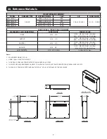
Страница 7: ...MODEL TRIP AIC WIRE RANGE SUT20KMBP NADER NDM1 125C 80 4 80A 10K 400VAC 1 10 1 AWG SUT20KMBPX NDM1 125C 80 4 80A SUT30KMBP NDM1 125C 125 4 125A SUT40KMBPX NDM1 125C 125 4 125A WIRE RANGE TORQUE VALUE...

Страница 8: ...shall be between the manufacturer and the user Terms and conditions may vary These integrated products include but may not be limited to the following products Batteries Inverters and UPS Systems Use...

Страница 9: ...sibles 11 4 3 Da os Ocultos 11 4 4 Devoluci n de Mercanc a Da ada 11 5 Visi n General del Sistema 11 6 Especificaciones del Sistema 11 6 1 El ctricas 11 6 2 Ambientales 11 6 3 Especificaciones General...

Страница 10: ...quipo sin la autorizaci n de Tripp Lite podr an generar da os en el equipo lesiones f sicas o muerte Nunca trabaje con equipos el ctricos mientras est n conectados a la alimentaci n Desconecte el equi...

Страница 11: ...los da os del embarque Tripp Lite no es responsable por da os durante el embarque 4 4 Devoluci n de Mercanc a Da ada Si el equipo se da a y necesita devolverlo a Tripp Lite para su reparaci n un repre...

Страница 12: ...coloque el equipo contra un techo que no sea ign fugo Deje un espacio de 91 cm 3 pies entre el techo y el equipo excepto que se incluya un escudo a prueba de fuego adecuado Verifique tambi n que la u...

Страница 13: ...tro del equipo est incluido un juego de planos para la configuraci n espec fica del equipo Consulte los planos del equipo en la Secci n 10 Materiales de Referencia Antes de energizar el equipo debe se...

Страница 14: ...SW1 SW1 SW2 SW2 POSICI N 1 OPERACI N NORMAL POSICI N 1 EN DERIVACI N EXTERNA SW3 SW3 Antes de instalar o realizar tareas de mantenimiento en este equipo es muy importante leer este manual y asegurarse...

Страница 15: ...AKER DISPARO AIC RANGO DE CABLE SUT20KMBP NADER NDM1 125C de 80 4 80A 10 K 400VCA 1 10 1 AWG SUT20KMBPX NDM1 125C de 80 4 80A SUT30KMBP 125 NDM1 125C 4 125A SUT40KMBPX 125 NDM1 125C 4 125A RANGO DE CA...

Страница 16: ...s y condiciones pueden variar Estos productos integrados incluyen pero pueden no estar limitados a los siguientes productos Bater as Inversores y Sistemas UPS No se recomienda el uso de este equipo en...

Страница 17: ...cach s 19 4 4 Retour de marchandises endommag es 19 5 Aper u du syst me 19 6 Caract ristiques techniques du syst me 19 6 1 lectricit 19 6 2 Conditions environnementales 19 6 3 Caract ristiques techni...

Страница 18: ...on l quipement sans l autorisation de Tripp Lite pourrait causer des dommages l quipement des l sions corporelles ou la mort Ne jamais effectuer des travaux sur de l quipement lectrique qui se trouve...

Страница 19: ...l exp dition 4 4 Retour de marchandises endommag es Si l quipement est endommag et doit tre retourn Tripp Lite pour tre r par un repr sentant fournira des instructions de m me qu un num ro d autorisa...

Страница 20: ...plafond et l quipement moins qu un cran l preuve du feu ne soit fourni V rifier galement que l emplacement s lectionn offrira des espaces de travail conform ment l article 110 26 du Code national de l...

Страница 21: ...s sous tension Un ensemble de dessins pour la configuration sp cifique de l quipement est inclus l int rieur de l quipement Se r f rer aux dessins de l quipement dans la Section 10 Documentation de r...

Страница 22: ...r des instructions de connexion SW1 SW1 SW2 SW2 POSITION 1 FONCTIONNEMENT NORMAL POSITION 1 EN D RIVATION EXTERNE SW3 SW3 Avant de proc der l installation ou l entretien de cet quipement il est extr m...

Страница 23: ...R D CLENCHER AIC PLAGE DE CALIBRES DE FIL SUT20KMBP NADER NDM1 125C 80 4 80 A 10K 400VAC 1 10 1 AWG SUT20KMBPX NDM1 125C 80 4 80 A SUT30KMBP NDM1 125C 125 4 125 A SUT40KMBPX NDM1 125C 125 4 125 A R CA...

Страница 24: ...tilisateur Les modalit s peuvent varier Ces produits int gr s incluent sans s y limiter les produits suivants les batteries les inverseurs et les onduleurs Il n est pas recommand d utiliser cet quipem...

Страница 25: ...ww tripplite com support 2019Tripp Lite 1 26 2 26 2 1 26 3 26 4 27 4 1 27 4 2 27 4 3 27 4 4 27 5 27 6 27 6 1 27 6 2 27 6 3 27 7 4 7 1 28 7 1 1 28 7 1 2 28 7 1 3 28 7 1 4 28 7 2 28 7 2 1 28 7 2 2 28 7...

Страница 26: ...26 Tripp Lite Tripp Lite 3 1 2 2 1 Tripp Lite www tripplite com support Tripp Lite www tripplite com www tripplite com support...

Страница 27: ...ripp Lite RMA Tripp Lite RMA Tripp Lite SUT20KMBP SUT20KMBPX SUT30KMBP SUT40KMBPX SUT20KMBP SUT20KMBPX SUT30KMBP SUT40KMBPX 80 125 4 6 1 SUT20KMBP SUT30KMBP 208 120 3 4 SUT20KMBPX SUT40KMBPX 400 3 4 6...

Страница 28: ...28 7 7 1 7 1 1 7 1 2 7 1 3 3 240 SUT20KMBP SUT30KMBP 400 SUT20KMBPX SUT40KMBPX 7 1 4 7 2 Tripp Lite 7 2 1 90 110 26 NEC 6 2 7 2 2 110 13 NEC 8 5 7 2 3 10 75 C 75 C 75 C 250 NEC...

Страница 29: ...29 7 300 20 NEC 7 2 4 10 1 2 3 4 5 6 7 8 7 2 5 80 100...

Страница 30: ...30 8 9 SW2 ON OFF ON OFF OFF ON ON OFF ON OFF OFF ON SW1 SW2 SW3 1 2 SW2 3 SW3 4 5 SW1 1 SW1 SW1 2 SW3 3 SW2 4 SW1 SW1 SW2 SW2 1 1 SW3 SW3 Tripp Lite 9 1...

Страница 31: ...NDM1 125C 80 4 80 A 10 K 400 1 10 1 AWG SUT20KMBPX NDM1 125C 80 4 80 A SUT30KMBP NDM1 125C 125 4 125 A SUT40KMBPX NDM1 125C 125 4 125 A 14 2 0 14 8 5 6 6 2 0 13 6 14 2 0 14 8 5 6 6 2 0 13 6 14 2 0 14...

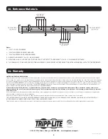
Страница 32: ...th Street Chicago IL 60609 USA www tripplite com support 11 Tripp Lite Tripp Lite Tripp Lite Tripp Lite Tripp Lite Tripp Lite Tripp Lite 19 03 373 93 3801_revB 10 1 SW1 2 SW2 3 SW3 4 4 14 2 AWG 5 1 14...

Отзывы: