4
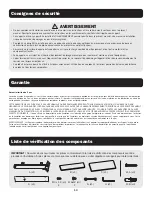
A
F
H
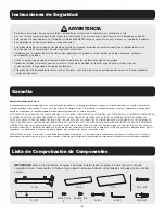
A (x1)
B (x1)
D (x1)
F (x4)
G (x1)
H (x1)
W-A (x4)
W-B (x4)
D
1
X
W-A
W-A
W-B
Note
: This product is designed to be installed on solid
concrete walls, masonry walls or wood walls.
Note
: This product is designed to be installed on solid
concrete walls, masonry walls or wood walls.
2
G
D
C (x1)
E (x4)
E
B
C
Assembly and Installation
>5mm
>5mm
1111 W. 35th Street, Chicago, IL 60609 USA • tripplite.com/support
21-01-258 93-3DCC_revA
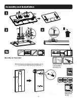
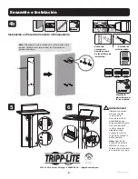
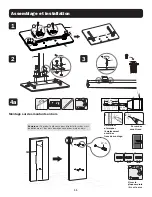
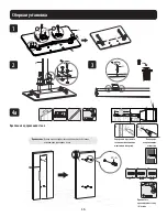
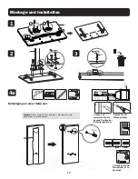
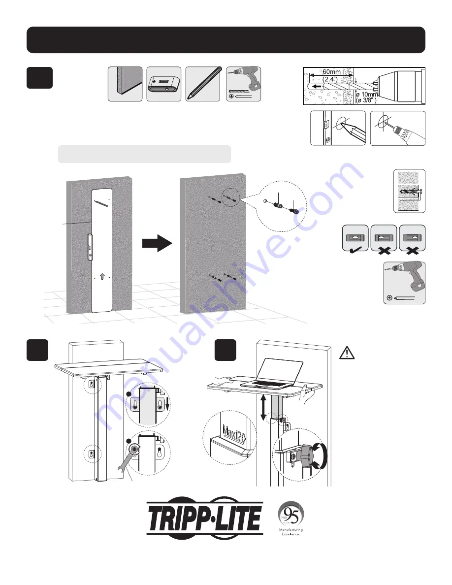
Screw the wall
plate (A) onto
the wall.
1
2
Find and mark the
exact location of
mounting holes.
Drill pilot holes.
A
F
H
A (x1)
B (x1)
D (x1)
F (x4)
G (x1)
H (x1)
W-A (x4)
W-B (x4)
D
1
X
W-A
W-A
W-B
Note
: This product is designed to be installed on solid
concrete walls, masonry walls or wood walls.
Note
: This product is designed to be installed on solid
concrete walls, masonry walls or wood walls.
2
G
D
C (x1)
E (x4)
E
B
C
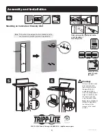
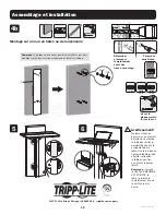
5
6
4b
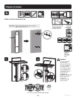
Warning!
Always use both hands
when adjusting the
table height to avoid
the possibility of it
accidentally falling.
Once the proper preset
height is reached, lock
the table in position
using the rotary knob.
Note:
When MAXIMUM
HEIGHT IS REACHED
the table will fully
release to the lowest
position.
Mounting on Concrete or Masonry Wall

