background image

12

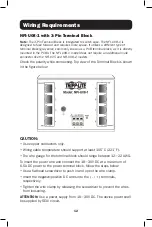
NFI-U08-1 with 3-Pin Terminal Block

Note: 

The 3-Pin Terminal Block is integrated to switch case. The NFI-U08-1 is 

designed to face forward and requires more space. It utilizes a different type of 
terminal block (gray color) commonly known as a PCB terminal block, as it is directly 

mounted in the PCBA. The NFI-U08-1 model does not require an additional male 
connector like the NFI-U05 and NFI-U08-2 models.

Check the polarity while connecting. Top view of the Terminal Block is shown 
in the figure below: 

Wiring Requirements

CAUTION: 

• Use copper conductors only.
• Wiring cable temperature should support at least 105˚C (221˚F).
•   The wire gauge for the terminal block should range between 12~22 AWG. 
To insert the power wire and connect the 18~30V DC at a maximum of 
0.5A DC power to the power terminal block, follow the steps below:
• Use a flathead screwdriver to push in and open the wire clamp.
•  Insert the negative/positive DC wires into the ( - / +) terminals, 

respectively.

•  Tighten the wire clamp by releasing the screwdriver to prevent the wires 

from loosening.

ATTENTION:

 Use a power supply from 18~30V DC. The device power shall 

be supplied by SELV circuit.

Содержание NFI-U05

Страница 1: ...te com support Copyright 2021 Tripp Lite All rights reserved Este manual está disponible en español en la página de Tripp Lite tripplite com Ce manuel est disponible en français sur le site Web de Tripp Lite tripplite com Dieses Handbuch ist in deutscher Sprache auf der Tripp Lite Website verfügbar tripplite com Owner s Manual Русскоязычная версия настоящего руководства представлена на веб сайте к...

Страница 2: ...ged high strength case Industrial temperature switch models support operating temperature range of 40 F to 167 F 40 C to 75 C Easy to read LEDs indicate connection and activity status for each port Meets the following IEEE standards o IEEE 802 3 10Base T o IEEE 802 3u 100Base T o IEEE 802 3 Auto Negotiation o IEEE 802 3x Flow Control Supports MAC address auto learning and auto aging Preinstalled d...

Страница 3: ... Cat5e 350 MHz Snagless UTP Cables N002 Series Cat5e 350 MHz UTP Ethernet Cables N200 Series Cat6 Gigabit Molded UTP Ethernet Cables N201 Series Cat6 Gigabit Snagless Molded UTP Ethernet Cables Optional Accessories ...

Страница 4: ...4 Product Overview NFI U05 5 Port Unmanaged Industrial Fast 10 100 Ethernet Switch Plug and Play Ruggedized DIN and Wall Mountable Top View Front View Side View 100 Mbps LNK ACT Grounding Screw Power ...

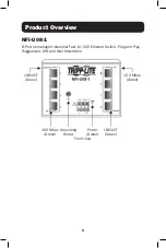
Страница 5: ...NFI U08 1 8 Port Unmanaged Industrial Fast 10 100 Ethernet Switch Plug and Play Ruggedized DIN and Wall Mountable Front View LNK ACT Green LNK ACT Green 18 30V DC 100 Mbps Green 100 Mbps Green Grounding Screw Power Green ...

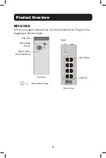
Страница 6: ...iew NFI U08 2 8 Port Unmanaged Industrial Fast 10 100 Ethernet Switch Plug and Play Ruggedized DIN Mountable DIN Rail Grounding Screw Power Input Terminal Block Top View Front View 100 Mbps LNK ACT Grounding Screw PWR ...

Страница 7: ...a rack enclosure The ambient temperature should not exceed 75 C 167 F Mounting the Switch Place the switch on the DIN rail from above using the built in slot Push the front of the switch toward the mounting surface until it snaps into place You will hear a click to indicate it has successfully snapped into place Dismounting the Switch Press the switch from the top then pull out the lower edge of t...

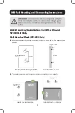
Страница 8: ...on for NFI U05 and NFI U08 1 Only Wall Mounted Mask NFI U05 Only 1 Mount the switch by using mounting holes on the wall at the appropriate places 2 The switch can be wall mounted either vertically or horizontally Mounting holes for NFI U05 Mounting Holes for Drawing of NFI U05 Screw Installation Distance Horizontal Direction Installation Straight Direction Installation 50 mm 1 5 mm 3 mm 50 mm Moun...

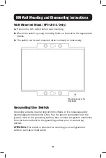
Страница 9: ...lly or horizontally Grounding the Switch Grounding and wire routing help limit the effects of line noise caused by electromagnetic interference EMI Run the ground connection from the ground screw to the grounding surface then connect the ground connection from the terminal block to the grounding surface prior to connecting devices ATTENTION This switch is intended for mounting on a well grounded s...

Страница 10: ...ot following polarity can damage your unit and void your warranty Please read and follow these guidelines Use separate paths to route wiring for power and devices If power wiring and device wiring paths must cross make sure the wires are perpendicular at the intersection point Note Do not run signal or communications wiring and power wiring through the same wire conduit To avoid interference wires...

Страница 11: ...of 0 5 N m 4 5 in lb with green connector The wire gauge for the terminal block should range between 12 24 AWG with green connector and 12 22 AWG with gray connector To insert the power wire and connect the 12 48V DC at a maximum of 0 15A DC power to the power terminal block follow the steps below Use a flathead screwdriver to loosen the wire clamp screws Insert the negative positive DC wires into...

Страница 12: ...Block is shown in the figure below Wiring Requirements CAUTION Use copper conductors only Wiring cable temperature should support at least 105 C 221 F The wire gauge for the terminal block should range between 12 22 AWG To insert the power wire and connect the 18 30V DC at a maximum of 0 5A DC power to the power terminal block follow the steps below Use a flathead screwdriver to push in and open t...

Страница 13: ...a maximum of 0 2A DC power To insert power wire and connect the 12 48VDC at a maximum of 0 2A DC power to the power terminal block follow these steps Use a flat head screwdriver to loosen the wire clamp screws Insert the negative positive DC wires into the PWR PWR terminals respectively Tighten the wire clamp screws to prevent the wires from loosening ATTENTION Use a power supply from 12 48VDC The...

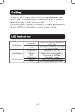
Страница 14: ...auto negotiation and auto MDI MDI X to eliminate the need for crossover cabling LED Indicators PWR Green Illuminated Power on by Terminal Block PWR or DC jack Off Terminal Block PWR DC jack fails or is unavailable 10 100 Green Illuminated Link speed is 100 Mbps Blinking Data is transmitting receiving Off Link speed is 10 Mbps LNK ACT Green Illuminated Copper port link up Blinking Data is transmitt...

Страница 15: ... T auto negotiation auto MDI MDI X Full Half Duplex and Flow Control LED PWR Green Power 100 Green Port 1 5 or 1 8 100 Mbps Ethernet speed LNK ACT Green Port 1 5 or 1 8 data transmitting receiving Environmental Operating Temperature 40 C to 75 C 40 F to 167 F Storage Temperature 40 C to 85 C 40 F to 185 F Operating Humidity 5 to 95 Non Condensing Storage Humidity 5 to 95 Non Condensing Operating A...

Страница 16: ...o the above limitations or exclusions may not apply to you This warranty gives you specific legal rights and you may have other rights which vary from jurisdiction to jurisdiction WARNING The individual user should take care to determine prior to use whether this device is suitable adequate or safe for the use intended Since individual applications are subject to great variation the manufacturer m...

Страница 17: ...n If this equipment does cause harmful interference to radio or television reception which can be determined by turning the equipment off and on the user is encouraged to try to correct the interference by one or more of the following measures Reorient or relocate the receiving antenna Increase the separation between the equipment and receiver Connect the equipment into an outlet on a circuit diff...

Страница 18: ...18 ...

Страница 19: ...19 ...

Страница 20: ...20 1111 W 35th Street Chicago IL 60609 USA tripplite com support 21 06 183 933E0E_RevC ...

Отзывы: