


4
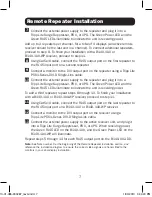
Standard Installation
Note:
1. Test to make sure that the entire installation works properly before pulling cables through
ceilings/walls.
2. 24AWG, Solid Wire Cat5e/6 cable, such as Tripp Lite’s N202-Series, is required to achieve
maximum distance and resolution.
3. The signal from input port A is transmitted to RJ45 output ports 1A and 2A. The signal from
input port B is transmitted to RJ45 output ports 1B and 2B. For your Dual Display installation
to appear correctly in extended screen mode, locate the monitor connected to RJ45 port 1A
next to the monitor connected to RJ45 port 1B. Likewise, locate the monitor connected to
RJ45 port 2A next to the monitor connected to RJ45 port 2B.
B140-002-DD
B140-1P0
B140-1P0-WP
B140-1A0-WP
B140-1A0
D
VI O
VER Cat5
EX
TEND
ER
RE
MO
T
E
UNIT
MODE
L: B1
40
-1
P
0
Up to 100 ft. at 1920 x 1080 @ 60Hz
Up to 50 ft. at 1024 x 768 @ 60Hz
Up to 150 ft. at 1920 x 1080 @ 60Hz
Up to 200 ft. at 1024 x 768 @ 60Hz
1
Make sure power to the DVI source is turned off.
2
Connect the first DVI port from the source to DVI input port A.
3
Connect the second DVI port from the source to DVI input port B.
4
Connect the external power supply to the B140-002-DD and plug it
into a Tripp Lite Surge Suppressor, Power Distribution Unit (PDU), or
Uninterruptible Power Supply (UPS). When receiving power, the Green
RJ45 LEDs on the B140-002-DD will illuminate.
13-01-085-933287_revA.indd 4
1/30/2013 3:44:18 PM


