background image

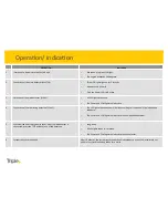
Synchroniza3on   of   the   Shut-­‐off


unit   with   the   network   and   the   connected   detectors   

is   essen3al   to   proper   opera3on   of   the   system   and   prevents   random   opera3on   by   

adjacent   systems.   Read   carefully   the   instruc3ons   and   follow   them   precisely:   

Coordina3on   of   the   communica3on   ID   No.   of   the   Shut-­‐off


unit   with   the   detectors   is   

part   of   this   process.   A   10-­‐minute   set   3me   is   defined   within   the   system   to   enable   
comple3on   of   the   synchroniza3on   process.      


The   first   detector   to   be   installed   is   the   main   detector   (MASTER).   We   recommend   

posi3oning   the   master   detector   closest   to   the   Shut-­‐off   unit   and   the   most   visual   

rela3ve   to   it.   The   process   will   commence   upon   installa3on   of   the   baYery   within   the   

Shut-­‐off   unit.   

System's   component   synchroniza3on   and   ac3va3on   

Содержание NGL

Страница 1: ...NGLTM Gas Product Installa3on Instruc3ons NGL INST 001E ...

Страница 2: ... Complies with standards FCC CE EN 50194 EN 50270 EN 300 EN 301 ISO9001 System descrip3on The NGLTM wireless detec3on and preven3on system was designed to detect gas leakage and shut down the gas supply by way of wireless communica3on Each installa3on may include up to 6 different detectors with one that would be defined during the detec3on as main detector MASTER and one Shut off unit to be installe...

Страница 3: ...1 Shut off unit 2 Adapter between the Shut off unit and the gas valve 3 Gas detector 4 CR123 baYery 5 Installa3on Instruc3ons Content of the package 1 2 3 4 5 ...

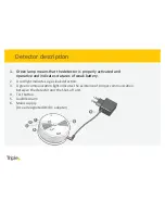
Страница 4: ...es statuses of weak baYery 2 A red light indicates a gas leak detec3on 3 A green communica3on light indicates the existence of proper communica3on between the detector and the Shut off unit 4 Test buYon 5 Audible Alarm 6 Mains supply Use a designated AC DC adapter Detector descrip3on ...

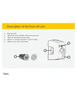
Страница 5: ...Main gas unit 2 Adapter to be installed in the main gas unit 3 Manual opening closing handle 4 BuYon for manual release to Closed state 5 BaYery cover not presented Descrip3on of the Shut off unit 2 1 3 4 ...

Страница 6: ...tector loca3on recommenda3ons Natural gas is lighter than air hence the detector should be located over the topmost window or door aperture but no more than 30 cm beneath the ceiling level Liquefied petroleum gas LPG is heavier than air hence the detector should be located below the level where a poten3al gas leak may occur and no more than 30 cm above floor level The NG or LPG detector should be lo...

Страница 7: ...any other place that may be subject to drads such as an air extrac3on fan or ven3la3on aperture Anywhere out of a structure Where temperatures may drop below zero degrees cen3grade or exceed 55 degrees cen3grade Where it may be subject to impact or damage When the sensor is installed in an area with rough working condi3ons such as extra wet kitchens and laundry rooms it should be protected by a tr...

Страница 8: ...s two holes on the wall 6 Drill two holes using a wood or concrete drill or used drywall studs 7 AYach the detector s mount to the wall using 2 x 5 mm screws 8 AYach the detector onto the mount and turn it slightly to the right un3l it is locked into its place 9 This is how the result should be 10 Connect the detector to the power outlet and ensure that all 3 LED lights turn on and a clear beep so...

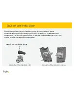
Страница 9: ...aintaining a direct line of sight between the components The Shut off unit should not be installed in closed metal cases as it may reduce the effec3ve range of communica3on Shut off unit installa3on stages Connec3on of the valve to the base unit Dismantling of the original valve unit Shut off unit installa3on ...

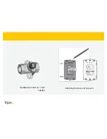
Страница 10: ...ASaching the base unit to a wall Installa3on of the 1 2 3 8 adapter ...

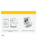
Страница 11: ...Inser3ng the baSery and the LED indicator Installa3on of the valve front unit and performing a manual test ...

Страница 12: ... ID No of the Shut off unit with the detectors is part of this process A 10 minute set 3me is defined within the system to enable comple3on of the synchroniza3on process The first detector to be installed is the main detector MASTER We recommend posi3oning the master detector closest to the Shut off unit and the most visual rela3ve to it The process will commence upon installa3on of the baYery within ...

Страница 13: ...4 Connec3on of the remaining detectors SLAVE The LED light of each detector will blink according to its posi3on in the installa3on sequence The Power and COM lights remain ac3ve in each iden3fied detector 5 Synchroniza3on of the system Ac3ve ader the last detector is connected press the TEST buYon of one of the detectors Long beep All the lights are on for a second The Power and COM lights remain a...

Страница 14: ...30 seconds and reconnect the unit Press the TEST buYon in each detector for 15 seconds Disconnect the unit from the main power supply wait approximately 30 seconds and reconnect the unit Remove the baYery from the Shut off unit Wait 30 seconds Reinstall the baYery in the Shut off unit Restart the synchroniza3on process Synchroniza3on reset Reset HEAD ...

Страница 15: ...io communica3ons However there is no guarantee that interference will not occur in a par3cular installa3on If this equipment does cause harmful interference to radio or television recep3on which can be determined by turning the equipment off and on the user is encouraged to try and correct the interference by one or more of the following measures Reorient or relocate the receiving antenna Increase ...

Страница 16: ...on Modifica3ons FCC 15 21 Changes or modifica3ons to this equipment not expressly approved by Triple Plus LTD may void the user s authority to operate this equipment RF Exposure info FCC 2 1093 This equipment has been approved for mobile applica3ons where the equipment should be used at distances greater than 20cm from the human body with the Excep3on of hands wrists feet and ankles Opera3on at dist...

Отзывы: