


TMCM-1141 Hardware Manual (Rev. 1.06 / 2015-JAN-09)
9
www.trinamic.com
3.2.1.2
RS485
For remote control and communication with a host system the TMCM-1141 provides a two wire RS485 bus interface.
For proper operation the following items should be taken into account when setting up an RS485 network:
1.
BUS STRUCTURE
:
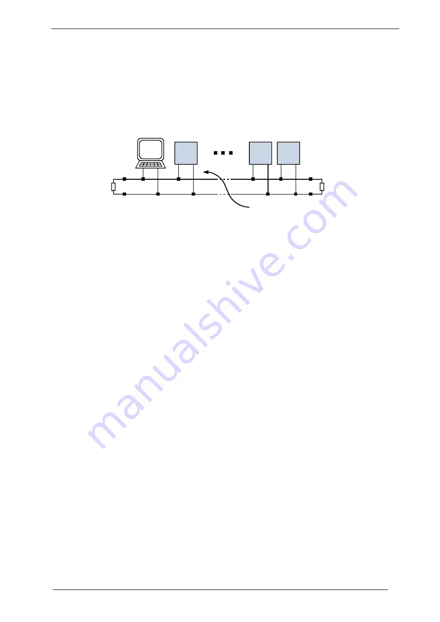
The network topology should follow a bus structure as closely as possible. That is, the connection between
each node and the bus itself should be as short as possible. Basically, it should be short compared to the
length of the bus.
c:>
node
1
node
n
- 1
node
n
Host
Slave
Slave
Slave
RS485
termination
resistor
(120 Ohm)
termination
resistor
(120 Ohm)
}
keep distance as
short as possible
Figure 3.3: Bus structure
2.
BUS TERMINATION
:
Especially for longer busses and/or multiple nodes connected to the bus and/or high communication
speeds, the bus should be properly terminated at both ends. The TMCM-1141 does not integrate any
termination resistor. Therefore, 120 Ohm termination resistors at both ends of the bus have to be added
externally.
3.
NUMBER OF NODES
:
The RS485 electrical interface standard (EIA-485) allows up to 32 nodes to be connected to a single bus.
The bus transceivers used on the TMCM-1141 units (hardware V1.2: SN65HVD3082ED, since hardware
V1.3: SN65HVD1781D) have a significantly reduced bus load and allow a maximum of 255 units to be
connected to a single RS485 bus using TMCL firmware.
Please note: usually it cannot be expected to get
reliable communication with the maximum number of nodes connected to one bus and maximum supported
communication speed at the same time. Instead, a compromise has to be found between bus cable length,
communication speed and number of nodes.
4.
COMMUNICATION SPEED:
The maximum RS485 communication speed supported by the TMCM-1141 is 115200 bit/s for hardware
version 1.2 and 1Mbit/s for hardware version 1.3. Factory default is 9600 bit/s.
Please see separate TMCM-
1141 TMCL firmware manual for information regarding other possible communication speeds.
5.
NO FLOATING BUS LINES:
Avoid floating bus lines while neither the host/master nor one of the slaves along the bus line is transmitting
data (all bus nodes switched to receive mode). Floating bus lines may lead to communication errors. In
order to ensure valid signals on the bus it is recommended to use a resistor network connecting both bus
lines to well defined logic levels.
There are actually two options which can be recommended:
Add resistor (Bias) network on
one
side of the bus, only (120R termination resistor still at
both
ends):