


SIXpack 2 – Manual (V1.10 / January 29
th
, 2010)
29
6.3.2
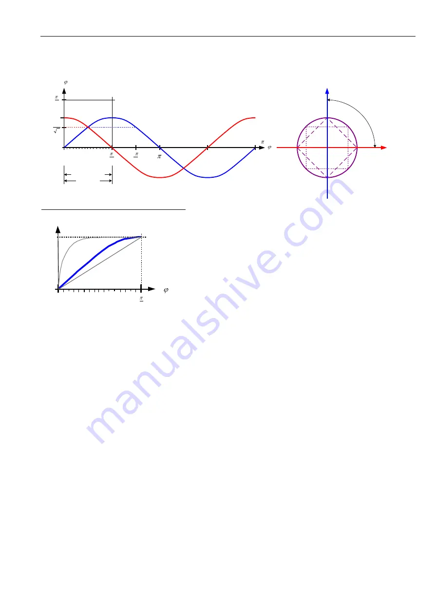
Adapting the microstep-table to the motor characteristics
alternative motor characteristics (s. CMD $17)
Most motors have varying microstep lengths, due to this
the motor would drive discontinuously for a sin -/ cos -
current. In order to reach a smoother run, you can drive
the motor with an adjusted current, so that the motor’s
characteristics can be compensated. This current curves
are generated with the 16 values in the table set via
CMD $17, which describe a quarter period.
(s. left)
6.4
Reference point adjustments
Additionally to the standard configurations for end and reference switches described in chapter 5.5 there are many
possibilities to adept these settings to an individual configuration.
6.4.1
Coordinate plane of an axis
In standard configuration the position counter for each axis is zero. The target position value for a movement is
the absolute number of micro steps from zero to target position. The maximum value of micro steps per axis is
adjusted by variable
Poslimit
in command
SetMotorParameters
(CMD $15, SQPack-Tab “Reference search”.
6.4.2
Reference point / reference switch
The reference point is defined by a mechanic stopper or a reference switch. If an active reference switch is used,
in opposition to the recommended passive switch (refer to chapter 5.5.2), the Flag MT_NULLPOSITIVE (command
SetMotorParameters
, CMD $15) has to be set to zero (MT_NULLPOSITIVE = 0).
6.4.3
Moving zero-point
In basic configuration the reference point is the zero-point, also. With the command
SetNullPointOffset
(CMD
$18)an offset of the zero-point is possible. This can be important if for example the reference switch is at the
center of the axis but the programming allows positive values, only.
x
0
2
0
2
4
3
)
(
f
box
rho
m
b
cir
cle
1
2
y
up to 16 micro steps
1 full step
16
mi
cro
st
ep
s w
ith
in
a q
ua
dra
nt
1 fu
ll ste
p
2
1
2
)
(
f
(16 values for generating the current)
A
0
0
step
full
/
rectangle
(1)
triangle
(3)
(default)
sinus
(2)
(3)
(1)
(2)


