


SIXpack 2 – Manual (V1.10 / January 29
th
, 2010)
11
5.2.3
Baudrate of serial interface
The baud rate of the serial interface is set via jumper JP1 and JP2 (refer Figure 5.1).
JP1
JP2
Baud rate RS232/RS485
Baud rate CAN
X
X
9600
1 Mbit/s (*)
-
X
57600
500 kbit/s (*)
X
-
38400
125 kbit/s (*)
-
-
19200
250 kbit/s (default)(*)
Table 5.1: Adjustment of baudrate with jumpers
(*): The SIXpack 2 has an internal buffer for 16 CAN commands which need about 2ms execution time each. This
might limit the maximum data throughput.
The command
GetInputValues
(SQPack-Tab I/O, $30) provides the actual jumper configuration in the variable
AllInputs
.
Bit 6 = Jumper1, Bit 7 = Jumper2
The baud rate for RS232/485 can be modified by software also. This setting is not stored permanently.
In order to get the actual jumper-configurations send CMD $30.
5.2.4
Termination of CAN/RS485
Each interface can be terminated by setting the jumpers “TERM CAN” and “TERM RS485” (refer Figure 5.1).
5.2.5
Seven-segment display
The seven segment display shows the number of active motors. With an appropriate power supply a “0” is shown
at start. The decimal point indicates that a reference search at any motor is accomplished.
If a malfunction occurs the display shows “8”, “C” or “F”. Try to restart the SIXpack 2.
5.2.6
Driver enable
The jumper “Driver enable” (close to the motor connectors) enables (jumper set) or disables (jumper open) the
drivers for all motors. Pin2 of the jumper is GND, and Pin1 has a 10k pullup to +5V with a CMOS logic gate level. It
can be used as an interlock/motor enable switched by opto coupler or relay. If the drivers are disabled, i.e. jumper
open, it is safe to disconnect the motors while power on and retain the actual settings of the SIXpack 2.
Hint: It is possible to use a switch to enable/disable the drivers.
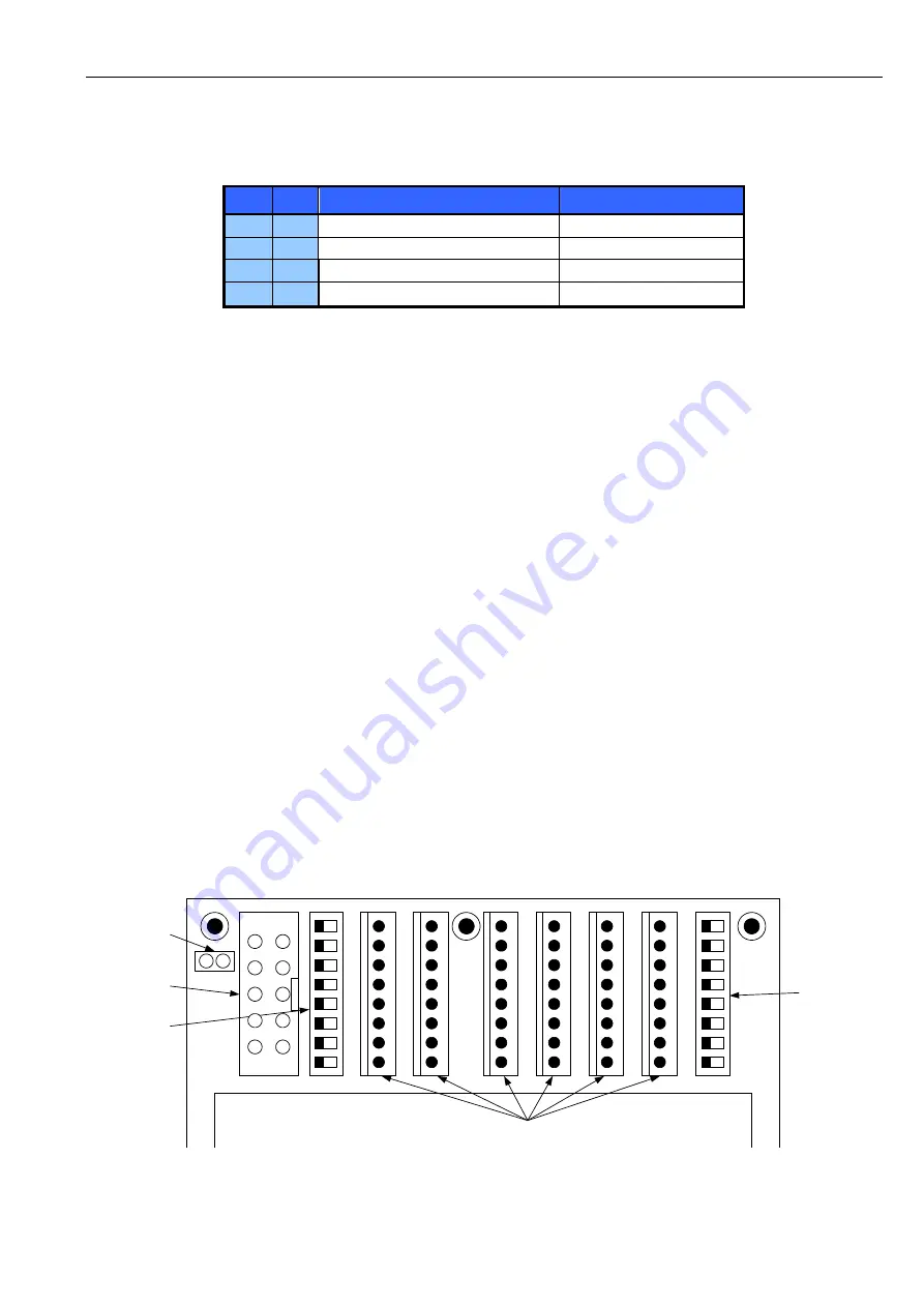
Driver enable
Multifunctional
"RS232"
DIP-switches:
1: M2 I 1
2: M2 I 0
3: M1 I 1
4: M1 I 0
5: MD246
6: MD135
7: 2A_246
8: 2A_135
DIP-switches:
1: M6 I 1
2: M6 I 0
3: M5 I 1
4: M5 I 0
5: M4 I 1
6: M4 I 0
7: M3 I 1
8: M3 I 0
SIXpack 2
3
1
2
4
5
6
7
8
1
2
1
2
3
4
5
6
7
8
9
10
3
1
2
4
5
6
7
8
Motor connectors
Figure 5.2: Driver enable, DIP switches and motor connectors


