


PD-109-57 / TMCM-109-57 Manual (V1.10 / October 17th, 2007)
9
Copyright © 2006, TRINAMIC Motion Control GmbH & Co. KG
3.3.2 Connector 2: RS232 and additional I/O
The RS232 interface and all other inputs and outputs of the module can be connected here. These are
the limit switches, a general purpose input and a general purpose output. The limit switch inputs are
equipped with internal pull-up resistors, so they have to be connected to GND via normally closed
switches, if enabled via software. The general purpose input can either be used as a digital TTL input
or as an analogue input with a voltage range of either 0..5V or 0..10V. This voltage range is
selectable by software. The general purpose output is an open collector output for a maximum
current of 250mA. Freewheeling diodes connected to the supply voltage are also included so that e.g.
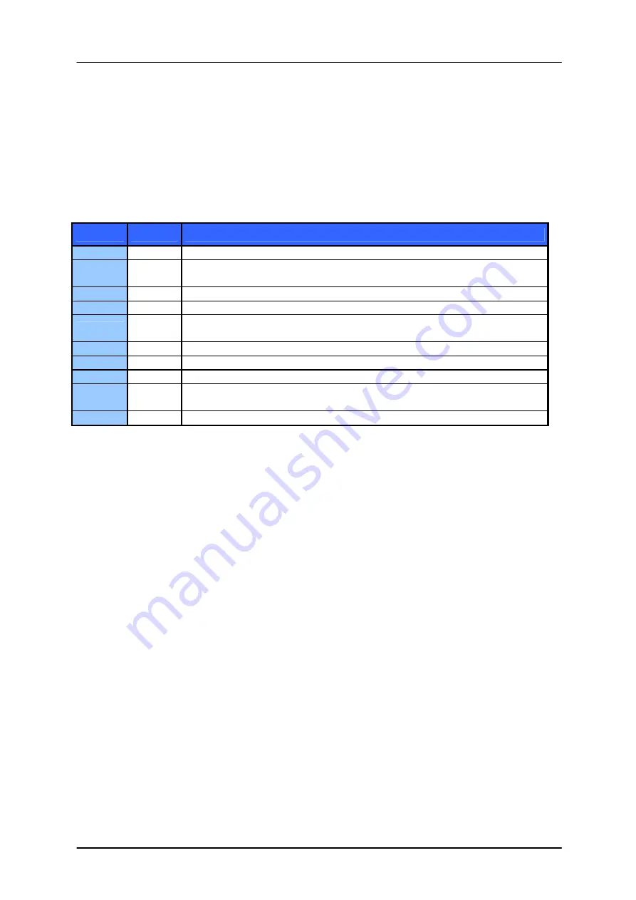
a 24V relay or a coil can be connected directly. The pin assignment of this connector is as follows:
Terminal
Name
Function
1
GND Ground
2
IF select Interface selection:
Leave open to use RS232, connect to ground to use RS485.
3
TXD
RS232 TxD (output)
4
RXD
RS232 RxD (input)
5
GPO0
General purpose output 0 (same as connector 1, terminal 1)
(open collector, max. 250mA, max. 40V, 1K pullup to 5V integrated)
6
GPI0
General purpose input 0 (max. 5V)
7
StopR
Right limit switch input (integrated 10K pullup to 5V)
8
StopL
Left limit switch input (integrated 10K pullup to 5V)
9
+5V
+5V output (max. 150mA)
Can be used to supply 5V fan or optical switches.
10
GND Ground
Table 3.2: Connector 2
3.4 Connecting the Motor (Connector 3 and 4)
Normally, the TMCM-109 module comes mounted on a suitable stepper motor. Should you have a
module without a motor you can connect a two phase bipolar stepper motor yourself. To connect the
motor there are two screw terminals adjacent to a cable feed through hole on the board. Connect
one coil of the motor to one of the connectors and the other coil to the other connector. Please
always make sure that the module is disconnected from the power supply before connecting or
disconnecting a motor. Connecting or disconnecting a motor while the module is powered can
damage the module!
Connect one motor coil to connector 3 and the other motor coil to connector 4. The direction of the
motor shaft can be reversed by changing the polarity of
one
coil.
Do not connect or disconnect the motor while power on. Damage to the module
may occur.


