background image

CHECKING AND ADJUSTING THE WORKTOP FOR 

FLATNESS (continued). 


Adjust the surface flatness by adding packing 

pieces, made from 1.5mm-3mm (1/16” – 1/8”) 

thick rigid material such as PVC Foamboard, under 

the mounting plates during installation (see 3.3). 


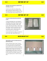
THE BASE LOCATING BRACKETS & MOUNTING 

PLATES 

The base locating brackets and mounting plates 

are designed to hold the base of the cutter firmly 

in place and provide a means to adjust the base 

for both flatness and alignment of the cutting 

groove.  Before fitting the brackets, check that the 

tips of the grub screws are aligned with the inside 

of the bracket.  These are factory set but may 

have moved in transit.  Check that the jacking 

screws are present and are finger tight. 

IF YOU ARE FITTING THE ATHENA 3 TO THE ATLAS 

FOR ATHENA TABLE PLEASE PROCEED TO 7.1 


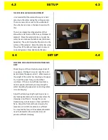
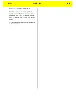
POSITIONING THE BASE LOCATING BRACKETS & 

MOUNTING PLATES 

Position a bracket & plate 10 cms (4”) inboard 

from either end of the line drawn as described in 

3.1, ensuring that the centre of the bracket is 

aligned with the pencil line and fix to the worktop 

using the screws provided.  Position the remaining 

brackets accurately along the line with equal 

spacing (B) between each bracket.  Check that all 

brackets are aligned correctly and if not, remove 

any incorrectly positioned brackets slightly to one 

side of the original position to create new screw 

holes. 


3.3   


BEFORE SET UP  


3.3 

3.4   


BEFORE SET UP  


3.4 

3.2   


BEFORE SET UP  


3.2 


Содержание ATHENA 110

Страница 1: ......

Страница 2: ...in writing Proof of purchase must be submitted to validate warranty coverage The warranty is in lieu of all other agreements and warranties expressed or implied THE MANUFACTURER DOES HEREBY EXPRESSLY...

Страница 3: ...nment 4 2 The rotating mechanism 4 3 The integral levelling adjustment 4 4 Checking and adjusting for flatness and grip 4 5 Building up the table top surface 5 Operation 5 1 Inserting the material to...

Страница 4: ...your machine check with the lists below and the photographs opposite to make sure that you have all the parts and that there is no damage Your machine comprises of the following items ATHENA A3 CUTTE...

Страница 5: ...of the cutter 70cms 28 A 90cms 36 110cms 44 A 130cms 52 160cms 64 A 180cms 72 210cms 84 A 230cms 92 260cms 104 A 280cms 112 310cms 124 A 330cms 132 360cms 144 A 380cms 152 Should you wish to use the...

Страница 6: ...factory set but may have moved in transit Check that the jacking screws are present and are finger tight IF YOU ARE FITTING THE ATHENA 3 TO THE ATLAS FOR ATHENA TABLE PLEASE PROCEED TO 7 1 POSITIONIN...

Страница 7: ...OOVE ALIGNMENT The cutter bar is guaranteed to be straight to within 0 4mm 016 along its full length If you need to adjust the cutting groove in the base to match this the base brackets provide the me...

Страница 8: ...Loosen by one full turn anti clock wise the four hexagon screws two at each end joining the fixed arms to the cutter base Now fully insert the two wood screws When not in use the cutter bar can be ro...

Страница 9: ...FLATNESS AND GRIP Check the grip of the cutter bar using a sheet of copy paper Starting at one end raise the cutter bar and place the paper under it When lowered the weight of the cutter bar should g...

Страница 10: ...been installed all that remains is to raise the level of the surrounding surface by 19mm 3 4 The best way of doing this is to add a new work top made from MDF or similar The worktop should not extend...

Страница 11: ...now ready to cut all materials of that thickness The flip stop is provided to prevent tough materials such as PVC Foamboard from moving during cutting If you are cutting a small piece of board place i...

Страница 12: ...our positions allowing materials up to 19mm 3 4 thick to be cut Fine adjustment of the blade depth can be carried out by undoing the BLADE CLAMP THUMB SCREW and moving the cartridge itself To cut ligh...

Страница 13: ...upported by a plastic cutting strip embedded in the base of the machine The blade guard makes it safe to handle but be careful as the blade is very sharp To change the cutting channel first raise the...

Страница 14: ...UTTING HEAD are made from a high quality polymer and under normal use will last for an extremely long time As they settle into position you may find a slight amount of side play this can be removed by...

Страница 15: ...of the brackets Slide the assembly left or right so that the holes in the fixed arms line up with holes in the support brackets fitted to the table Insert the four button head screws and nuts include...

Страница 16: ......

Отзывы: