1. Sun Shield
2. Front Cover
3. Zoom and Focus Lever
4. IR LED
5. Lens
6. Air Vent
7. Video Output Interface
8. Integrated Bracket
9. Reset Button
10. SD Card Slot
11. Power Interface
12. Network Interface
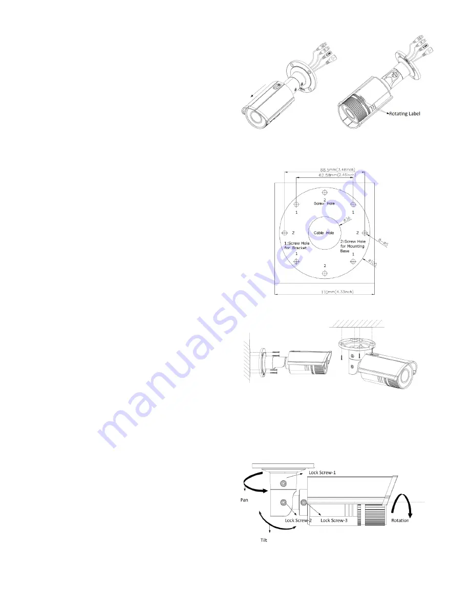
2. Drill the Holes
1. Attach the drill template (supplied) to
the wall where the camera is to be
mounted.
2. Drill screw holes in the wall according
to the drill template.
3 If you need to route cables through the
wall (or ceiling), cut a cable hole
according to the drill template.
4 Route the cables of the camera.
5 Secure the camera to the wall (or
ceiling) with expansion screws. (fig.7)
3. Viewing Angle Adjustment
Pan Adjustment (See fig.8)
Loosen lock screw-1.Adjust the panning
position of the camera. The adjusting range
is from 0 to 360 degrees.Tighten the lock
screw-1.
Tilt Adjustment (See fig.8)
Loosen lock screw-2. Adjust the tilting
position of the camera. The adjusting range
is from 0 to 90 degrees.Tighten the lock
screw-2.
Rotation Adjustment (See fig.8)
Loosen lock screw-3.Rotate the rotation
position to adjust the azimuth angle of the
image. The adjusting range is from 0 to 360
degrees.Tighten lock screw-3.
For detailed instructions please visit
www.triax.co.uk
Fig. 7
Fig. 8
Fig. 6
Fig. 5


