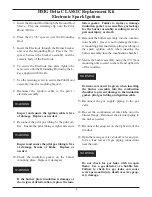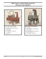
Identifying Pilot Assembly Series
If the pilot assembly is mounted on a vertical brack-
et which is attached to the burner neck, refer to
Series 1 Conversion instructions.
If the pilot assembly is mounted on a horizontal
bracket which is attached to the burner neck, refer
to Series 2 Conversion instructions.
HMG Delta CLASSIC Replacement Kit
Electronic Spark Ignition
2
Series 1 Pilot Assembly Instructions
Removal of the Burner and Existing Pilot
Assembly
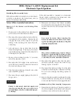
1. Ensure power to the unit has been disconnected
prior to removal of the burner assembly.
2. Disconnect the snap-set plug located on the bot-
tom right side of the windbox. Depress the tab
and grip the body of the snap-set to prevent
damage to the incoming wire leads when dis-
connecting.
3. Lift and remove the air inlet tube from the
blower housing flange. If necessary, disconnect
any air inlet piping connected to the unit prior to
removing the air inlet tube.
4. Remove silicon tubing from the “v” (vaccum)
side of the pressure switch.
5. Disconnect the 24V supply to the control mod-
ule at the male to female connecters located on
the wires near the gas valve.
6. Turn the main manual gas shut-off valve at the
unit to the OFF position.
7. Disconnect the gas supply piping at the inlet of
the gas valve.
Failure to disconnect electrical supply and
close the gas shut-off valve can cause severe
personal injury, death or substantial proper-
ty damage.
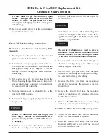
8. Dismount and remove the burner assembly
from the unit by removing the (2) 17mm mount-
ing nuts located to the left and right side of the
windbox.
Care must be taken when removing the
burner assembly from the unit as not to dam-
age the mounting plate insulation or the pilot
assembly and pilot tube.
The service technician may need to remove
the burner control module from the top of the
windbox to allow ease of removing the burn-
er assembly from the combustion chamber
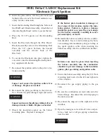
9. Disconnect the ignition cable from the pilot /
electrode assembly. Inspect the cable for any
damage, replace as needed.
8. Disconnect the pilot gas tubing from the pilot
assembly by loosening the compression fitting.
Use care not to damage the tubing, replace as
needed.
9. Remove the pilot assembly and bracket from the
vertical bracket by removing the (2) mounting
screws and nuts from the vertical support bracket.
Installation of New Pilot Assembly Components
1. Mount the new pilot hood / bracket assembly to
the vertical support on the burner neck using (2)
machine screws with lock washers and nuts.
NOTICE
WARNING
WARNING

