


Greenflame Wood Pellet Boiler 13-18kW
10
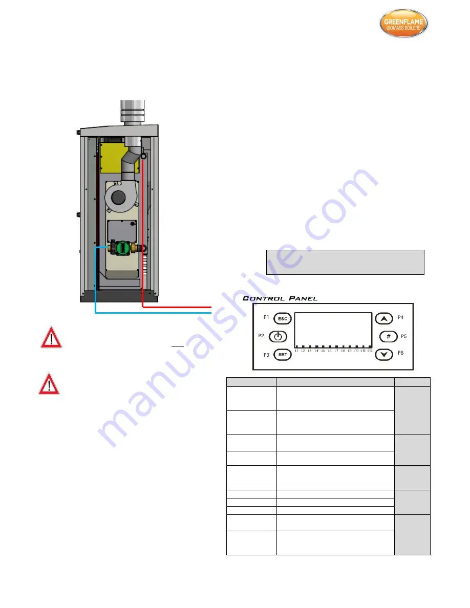
FUNCTION
DESCRIPTION
BUTTON
ON/OFF
Function:
Ignition, Extinguishing
by
pushing the button for 3 seconds until
the acoustic signal.
P2
UNBLOCK
Function:
unblock
. When the system is in
Block by pushing the button for 3
seconds until the acoustic signal.
MODIFY VALUES
INTO MENU
In modify mode change menus and
submenus values.
P4
P6
RUN ON MENU
AND SUBMENU
In Menu run on submenu and menu.
ESC
Function: Exit managed by pushing the
button if in a menu or a submenu. Out of
menu “Pump Test”
P1
MENU
Function: Enter in menu or in a submenu.
P3
MODIFY
Enter in modify mode into a menu.
SET
Save data in a menu.
ENABLE CHRONO
PROGRAMMING
In Chrono menu -> Chrono Program:
enables the selected program.
P5
KEYBOARD LOCK
To lock keyboard keys keep this button
pressed for 3 seconds. To unlock repeat
the same procedure.
4.5 Water Connections
The diagram below indicates the plumbing connections at
the rear of the boiler. The return connection is factory fitted
with a 25/6 standard pump.
Incorrectly sized expansion vessel will invalidate
the warranty. A minimum 18 litre vessel is
recommended for the boiler plus additional
expansion for heating and domestic hot water
system.
Ensure that the pre-charge in the vessel is equal to
the initial system fill pressure of between 1-1.5
bar.
The boiler can be plumbed into either an open vented
system (the maximum static head of water permissible is
90ft. (27.44m) or a sealed system. If plumbed into a sealed
system an appropriately sized expansion vessel should be
used and installed as per manufacturer’s instructions. The
expansion vessel should be sized based on the water
capacity in the boiler and the water in the entire heating
system.
The pump is on the return pipe work just before the boiler. It
is recommended that a by-pass pipe between the flow and
return is used with a valve to regulate the temperature of
the water returning to the boiler. Also, the system designer
should ensure that there is adequate provision in the system
for heat dissipation from the boiler during the shut-down /
extinguishing phase. An automatic air vent and pressure
relief valve must be fitted to the flow pipe work immediately
outside the boiler. The pressure relief valve should be piped
to a drain to prevent injury to the user or service technicians
if it is activated. All unused connections should be sealed
with blanking plugs. A non-return valve should be fitted to
prevent back siphonage.
Once the plumbing has been completed the system should
be fully flushed to clear any debris which may have become
lodged in the pipe work. The system should generally be
filled from the lowest point on the system to force any air to
the highest point where it can be vented. The flow pipe on
the boiler is fitted with a manual air vent for venting air from
the boiler. The system must then be filled and the pump can
be run continuously for a few hours to completely de-aerate
the system. Hold the ESC button on the controller for 3
seconds to activate the pump. Repeat the procedure to turn
it off. Only when the system has been fully vented can the
boiler be commissioned.
The Installation and the design of the central heating system
must be in accordance with BS EN 14336:2004: Heating
systems in buildings. Installation and commissioning of water
based heating systems. BS EN 12828:2003: Heating systems
in buildings. Design of water based heating systems. BS EN
12831:2003: Heating systems in buildings. Method for
calculation of the design heat load.
5. Control System
Always ensure that all connections are making a
watertight seal.