Triacta PowerHawk 6320 Скачать руководство пользователя страница 21

NOT

 FO

R DI

ST

RIBUTIO

N

 WI

THO

U

T T

H

CON

S

ENT 

OF 

TRIACTA PO

WER

Triacta Power Technologies PowerHawk 6320

Installation 

17

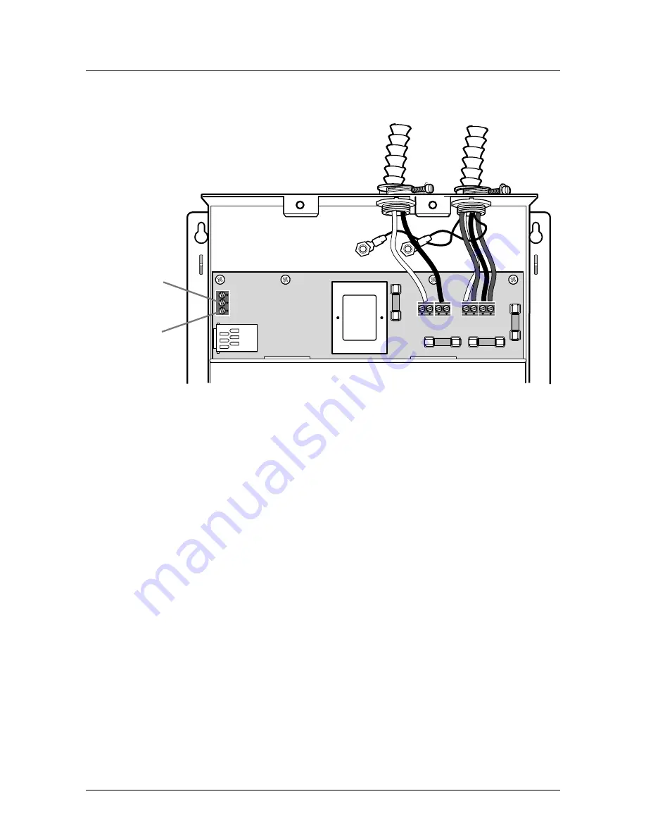
Figure 8:  PowerHawk 6320 Pulse Input Connection 

Start-up sequence for the PowerHawk 6320 meter

Once the CTs are connected, and the breaker is closed, the PowerHawk automatically starts up. 
The LCD on the front panel of the PowerHawk indicates the operating status of the unit as 
follows:

Initial power up message “PowerHawk 6320”

Once the internal configuration is complete, the display will show default information for 
the first meter

The initial report

To manually force the PowerHawk to report to


the Triacta Data Centre,


perform the following:

1.

Press and hold the Display button for 5 to 7 seconds until diagnostics mode is displayed, 
then release.

2.

Press the Display button until the “Send” command appears on the display.

3.

Press the right arrow button to manually force the PowerHawk to report meter data.
This will clear any old data from the PowerHawk memory and ensure that the time is set 
correctly.

PIN 2 

PIN 3

(GND) 

Содержание PowerHawk 6320

Страница 1: ...PowerHawk 6320 High Density Meter Installation Guide...

Страница 2: ...f authorized Triacta personnel Triacta products are intended for commercial uses The customer hereby agrees that the use sale licence or other distribution of the products for any such application wit...

Страница 3: ...cable in a 120 240V application 8 Using the auxiliary power input 11 Installing the current transformers 12 Using 5A CT converters with the PowerHawk 6320 meter 15 Connecting the phone line 16 Connec...

Страница 4: ...NOT FOR DISTRIBUTION WITHOUT THE CONSENT OF TRIACTA POWER Triacta Power Technologies PowerHawk 6320 ii Table of Contents...

Страница 5: ...description The PowerHawk 6320 high density meter is single phase poly phase and three phase devices with 20 individual meters All PowerHawk units are designed for residential commercial and industria...

Страница 6: ...NOT FOR DISTRIBUTION WITHOUT THE CONSENT OF TRIACTA POWER Triacta Power Technologies PowerHawk 6320 2 PowerHawk 6320 Meter Installation Guide Figure 1 PowerHawk front panel...

Страница 7: ...ge tolerance 108V to 127V Maximum current 125 mA 60 Hz Current probes 200 A 400 A 800 A Measurement accuracy Measurement Canada Approved Pulse input Dry form A and solid state form A compatible Intern...

Страница 8: ...ng topics are covered Pre installation check list on page 4 Site planning on page 5 Pre installation check list The following Triacta Power equipment is required for each installation PowerHawk 6320 h...

Страница 9: ...4 AWG 1 63 mm2 cable for single phase or poly phase PowerHawk installation small flat head screwdriver crimping tool 22 AWG to 18 AWG crimps wire strippers four 1 inch 25 mm 8 mounting screws suitable...

Страница 10: ...linder plugs 1 Remove the front cover from the PowerHawk by removing the four screws with a Phillips screwdriver Keep the cover and screws in a safe place for re installing 2 Mount the PowerHawk on th...

Страница 11: ...figuration must be Y Y Figure 2 shows a block diagram of a complete three phase 4 wire installation Figure 2 Typical three phase 4 wire installation H1 X1 H2 X2 H1 X1 H2 X2 H1 X1 H2 X2 C B A N N A B C...

Страница 12: ...ble For a three phase panel use a 4 wire red black blue white 14 AWG 1 63 mm2 cable Metallic flexible armored cable BX cable is recommended for commercial installations As a safety precaution the Powe...

Страница 13: ...terminal to breaker phase A red wire PowerHawk B terminal to breaker phase B black wire PowerHawk neutral terminal to neutral bar in panel white wire Earth wire to earth post using lug provided Phase...

Страница 14: ...l to breaker phase C blue wire PowerHawk neutral terminal to neutral bar in panel white wire Earth wire to earth post using lug provided Figure 4 PowerHawk 120 208V three phase wye service connection...

Страница 15: ...wer the unit through the auxiliary power input the shorting bars must be removed from the auxiliary power connector before connecting the reference voltage inputs The auxiliary power inputs are 120V a...

Страница 16: ...6 CTs are N Amp solid core CTs that are installed on existing connections Current transformers connect to the PowerHawk through the two 25 pair CT cables labeled Cable 1 and Cable 2 See Table 3 for t...

Страница 17: ...e severe injury and equipment damage 1 Connect the 25 pin amphenol connector of cable 2 to the PowerHawk connector located at the bottom of the unit and secure it in place with the retaining clips Rep...

Страница 18: ...P2 3 Black Orange P12 3 Black Blue P3 1 Black Brown P13 1 Green White P3 2 Black Yellow P13 2 Red Orange P3 3 Black Blue P13 3 Red Brown P4 1 Green Yellow P14 1 Red Yellow P4 2 Green Blue P14 2 Red Bl...

Страница 19: ...sure To connect the 5A CT to the converter on the PowerHawk 6320 follow these steps 1 Connect the X1 lead of the 5A CT to the shorting device 2 Connect the X2 lead of the 5A CT to the shorting device...

Страница 20: ...DHCP server the PowerHawk meter will be able to report using its factory default IP settings If there is no DHCP server refer to the PowerHawk meter Configuration Guide for instructions to configure...

Страница 21: ...p message PowerHawk 6320 Once the internal configuration is complete the display will show default information for the first meter The initial report To manually force the PowerHawk to report to the T...

Страница 22: ...ton scrolls one or more of the following information energy consumption in kWh for the selected meter power in Watts for the selected meter In Normal mode the right and left arrow buttons scroll the d...

Страница 23: ...eter 1 through N When the local IP address is shown on the LCD use the right and left arrow buttons to scroll through the following information remote host IP address default IP address default NetMas...

Страница 24: ...opy of Table 5 is provided with each PowerHawk 6320 Installation Record Table 4 Example of a completed Probe to Circuit Map Distributor Customer Address Postal code Phone number Installation date Inst...

Страница 25: ...be to circuit map Distributor Customer Address Postal code Phone number Installation date Installer name PowerHawk serial number PowerHawk MAC Probe Phase CT Brkr Description Description Brkr CT Phase...

Страница 26: ...Class A digital device pursuant to Part 15 of the FCC Rules These limits are designed to provide reasonable protection against harmful interference when the equipment is operated in a commercial envir...

Страница 27: ...must be returned to Triacta for repair If an equipment fault occurs do not attempt to repair the faulty component CAUTION All maintenance activities should be performed by qualified personnel only Do...

Страница 28: ...on equipment Symbol Description Indicates the supply wire protective earth also known as chassis ground for the secondary or feedthrough ground Indicates the supply wire protective earth also known a...

Страница 29: ...maximum altitude PowerHawk 3 maximum current PowerHawk 3 Measurement 3 measurement accuracy PowerHawk 3 measurement category PowerHawk 3 meter map recording 20 N NVM storage PowerHawk 3 O onboard Ethe...

Страница 30: ...ference voltage cable and power cable installation 120 V 240 V application 8 regulatory compliance 22 requirements safety 23 S safety certification 23 requirements 23 servicing equipment 23 site plann...

Страница 31: ......

Страница 32: ...T2 www triactapower com Triacta Power and the Triacta logo are trademarks of Triacta Power Technologies Inc Other trademarks that may be used in this document are property of their respective owners T...

Отзывы: