


Page 20
www.tri-m.com
TCB1000 Series User Guide Rev A
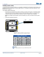
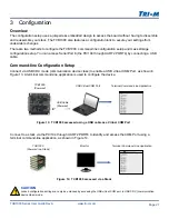
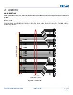
CAN Bus (CN12, CN13)
Two NXP SJA1000 CAN Bus controllers are configurable for BasicCAN and PeliCAN. Another feature is the
flexibility to access the CAN Bus as a socket network device. To configure the CAN Bus, please see “CAN
BUS MODE” on page 28.
The isolated CAN Bus transceivers:
•
provide high input impedance for maximum protection in harsh environments. An impedance setting
is built into the board and is enabled when pin 6 LOAD ON and pin 7 LOAD T are connected, and
unpowered nodes do not disturb the bus resulting in secure and reliable network signaling.
•
provide up to 2500V channel isolation, maximum speeds up to 1 Mb/s, and slope control to reduce
EMI.
•
have thermal shutdown protection.
2 Connectors
CAN Bus BUS (CN12, CN13)
Top
Bottom
Pin
Signal
Pin
Signal
1
N.C.
2
GND ISO
3
CAN Bus-
4
CAN Bus+
5
GND ISO
6
LOAD ON
7
LOAD T
8
+5VDC ISO
9
N.C.
10
N.C.
Note
To enable impedance (Z), connect LOAD ON and LOAD T.
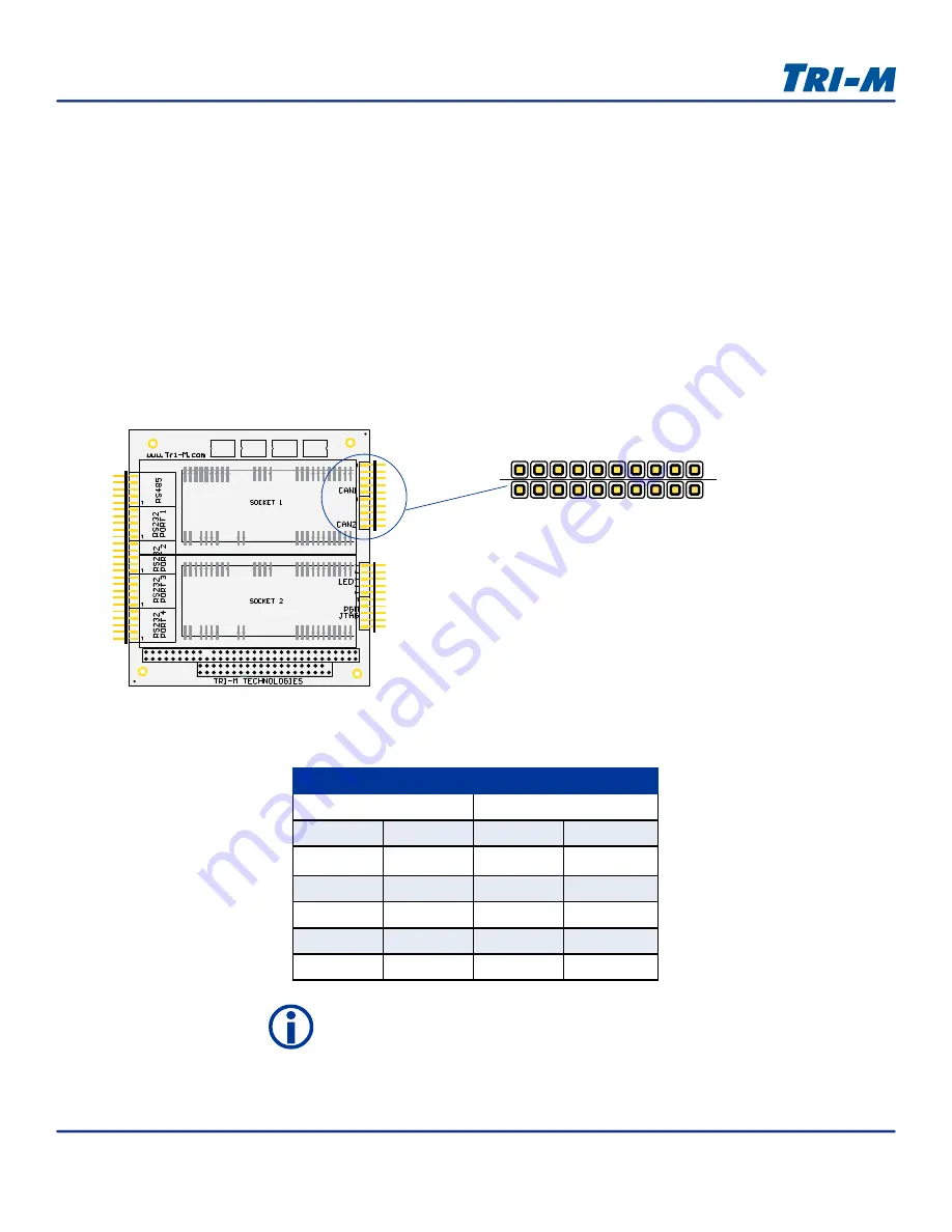
Figure 12: CN12 and CN13 Connector Pinouts
CN7
CN4
CN5
CN3
CN6
CN12
CN13
CN10
CN11
CN9
CN8
A32
C19
D19
B32
9
10
1
2
CN12
CN13
9
1