Toll-free (Canada & USA) 1-800-665-5600
2013-03-14
8
Direct: +1-604-945-9565
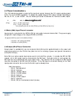
2.2 Power Considerations.
The +5V switching regulator is rated at 15A maximum output, however the +5V output supplies power
to the +12, and -12VDC regulators. To obtain the usable range of +5V output, “derate” according to
the use of +12, -5, and -12VDC. Use the following formulae to calculate the maximum usable output.
Where:
I[-12] = -12VDC current load
I[12] = 12VDC current load
Assuming 90 percent converter efficiency (actual efficiency may vary).
2.3 Main (CN2) Input Power Connector
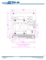
Input power is connected to the HE104-75W by removable connector blocks CN2. The power supply
accepts DC input voltages in the range of 6VDC to 40VDC.
Unregulated vehicle power is connected as follows:
-
Terminal 1:“hot” polarity (6-40VDC)
-
Terminal 2: Common (0VDC)
2.4 Output (CN4) Power Connector
Output power is available for use via connector block CN4 and is applied directly to the power and
ground connections on the PC/104 bus (refer to 2.2.3 for a listing of power and ground connections
on the PC/104 bus).
Note: SD is an opto-coupled input signal used to turn on/off the outputs. To enable the HE104-75W
outputs, a 6 to 40V signal must be connected to the SD input. If remote control is not required, the
SD input can be connected to the main power input. The common for the remote 6 to 40V signal
must be connected to the HE104-75W common. If the SD input is connected directly to the main
input power connector, the common for the SD input is already done.
CN4 Connections
-
CN4-1: Not populated
-
CN4-2: Common
-
CN4-3: -12VDC output
-
CN4-4: +12VDC output
-
CN4-5: Common
-
CN4-6: +5VDC output
-
CN4-7: Common
-
CN4-8: SD (i.e. maintained contact closure)
9
.
0
)
4
.
2
*
]
1
2
[
4
.
2
*
]
1
2
[
(
1
5
5
I
I
A
V
o
u
t
p
U
s
a
b
l
e
+
−
−
=
+

