- 14 -
MAINTENANCE
Your Tri-Clover pump will operate only if the rotors are
correctly installed. Therefore carefully follow the
installation procedure listed below.
TWO LOBE ROTORS
1.
Install 2D rotor onto top shaft.
Note:
It doesn't matter whether top shaft is pump
shaft or drive shaft.
2.
After installing 2D rotor, rotate shaft if necessary to
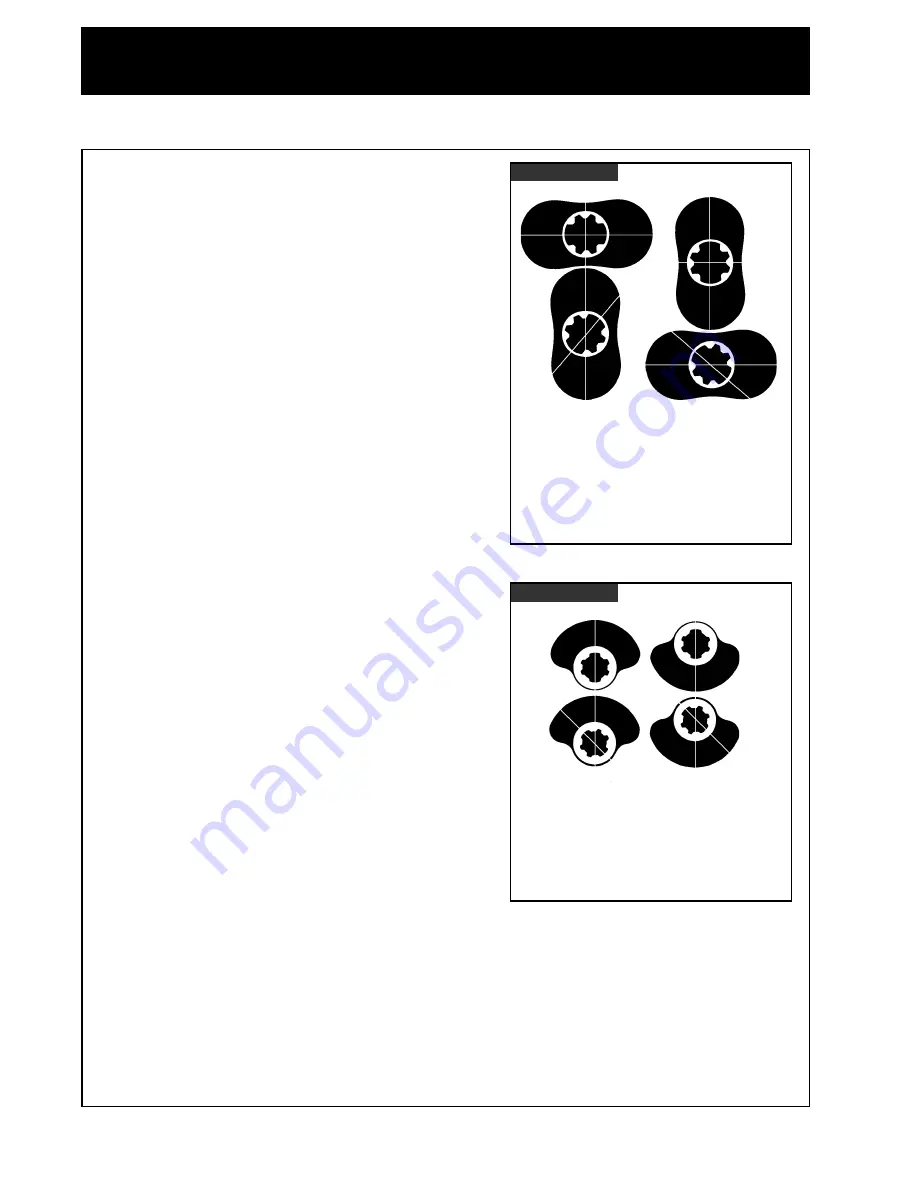
obtain spline relationship as shown in Figure 6.
3.
Install 2P rotor on lower shaft. 2P rotor must be
installed as shown in Figure 6. Rotors must form a
"T" shape when properly installed with the tip of
one rotor opposite the concave hub areas of the
mating rotor.
Note:
Pump cannot be operated unless the
above procedure is followed. If rotors are
not installed as shown, the pump will jam
when started resulting in damage to the
rotor or shaft.
SINGLE LOBE ROTORS
1.
Install 1D rotor onto top shaft.
Note:
It doesn't matter whether top shaft is pump
shaft or drive shaft.
2.
After installing 1D rotor, rotate shaft if necessary to
obtain spline relationship as shown in Figure 7.
3.
Install 1P rotor on lower shaft. 1P rotor must be
installed as shown in Figure 7. Large lobe of one
rotor must be next to small diameter or hub of
mating rotor.
Note:
Pump cannot be operated unless the
above procedure is followed. If rotors are
not installed as shown, the pump will jam
when started resulting in damage to the
rotor or shaft.
ROTOR INSTALLATION
Figure Six
Part 2D - Center line of wide spline
teeth is on center line of rotor
lobes.
Part 2P - Center line of wide spline
teeth is at a 45° angle with
center line of rotor lobes.
2D
2D
2P
2P
Figure Six
Part 1D -Center line of wide spline teeth
is on center line of rotor lobes.
Part 1P - Center line of wide spline teeth
is at a 45° angle with center
line of rotor lobes.
1D
1P
1P
1D


