background image


TE0714 TRM

Revision: v.55

Copyright ©  2019 Trenz Electronic GmbH

5 of 22

http://www.trenz-electronic.de

3 Table of Tables

Table 1: Initial delivery state of programmable devices on the module.......................................................................8

Table 2: Boot signals. .......................................................................................................................................................8

Table 3: JTAG signals. ......................................................................................................................................................9

Table 4: B2B I/Os ..............................................................................................................................................................9

Table 5: LED connection. ...............................................................................................................................................10

Table 6: Clock signals.....................................................................................................................................................10

Table 7: Power Consumption ........................................................................................................................................11

Table 8: Power Rails.......................................................................................................................................................12

Table 9: Bank Voltages...................................................................................................................................................12

Table 10: Connectors. ......................................................................................................................................................13

Table 11: Speed rating. ....................................................................................................................................................13

Table 12: Module absolute maximum ratings. ...............................................................................................................15

Table 13: Recommended Operating Conditions ............................................................................................................15

Table 14: Trenz Electronic Shop Overview .....................................................................................................................17

Table 15: Hardware Revision History ..............................................................................................................................18

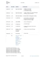
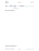
Table 16: Document change history ...............................................................................................................................18

Содержание TE0714 TRM

Страница 1: ...Online version of this document https wiki trenz electronic de display PD TE0714 TRM TE0714 TRM Revision v 55 Exported on 2019 03 04...

Страница 2: ...10 6 1 Quad SPI Flash 10 6 2 On board LED 10 6 3 Clock 10 7 Power and Power On Sequence 11 7 1 Power Consumption 11 7 2 Power Distribution Dependencies 11 7 3 Power On Sequence 11 7 4 Power Rails 12 7...

Страница 3: ...Electronic GmbH 3 of 22 http www trenz electronic de 12 1 Data privacy 21 12 2 Document Warranty 21 12 3 Limitation of Liability 21 12 4 Copyright Notice 21 12 5 Technology Licenses 21 12 6 Environmen...

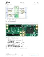
Страница 4: ...enz Electronic GmbH 4 of 22 http www trenz electronic de 2 Table of Figures Figure 1 TE0714 block diagram 7 Figure 2 TE0714 main components 7 Figure 3 Power Distribution 11 Figure 4 Power On Sequency...

Страница 5: ...3 JTAG signals 9 Table 4 B2B I Os 9 Table 5 LED connection 10 Table 6 Clock signals 10 Table 7 Power Consumption 11 Table 8 Power Rails 12 Table 9 Bank Voltages 12 Table 10 Connectors 13 Table 11 Spee...

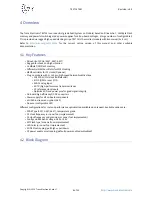
Страница 6: ...r for PL clocks Optional Plug on module with 2 100 pin high speed hermaphroditic strips 138 FPGA I O s Max 68 differential 5 IO s QSPI or user I O s XADC analog input 4 GTP high performance transceive...

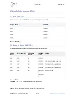
Страница 7: ...JM2 4 B2B connector Samtec Razor Beam LSHM 150 JM1 5 25 MHz oscillator U8 6 Single output low dropout linear regulator 1 2V_MGT U6 7 Single output low dropout linear regulator 1 0V_MGT U5 8 Low jitter...

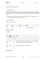
Страница 8: ...ignals on the board to board B2B connector Signal Direction Signal State Description BOOTMODE input high or open Master SPI x4 Mode low or ground Slave SelectMAP PROG_B input pulsed low Clear FPGA con...

Страница 9: ...B2B Pin TCK JM1 89 TDI JM1 85 TDO JM1 87 TMS JM1 91 Table 3 JTAG signals 5 2 Board to Board B2B I Os FPGA bank number and number of I O signals connected to the B2B connector FPGA Bank B2B Connector I...

Страница 10: ...te depends on the bus width and clock frequency used 6 2 On board LED There is one LED on TE0714 module LED Color FPGA Notes D4 Red K18 User programmable Table 5 LED connection 6 3 Clock Cloc k Defaul...

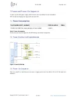
Страница 11: ...with nominal of 3 3V 7 1 Power Consumption Test Condition 25 C ambient VIN Current mA Notes TE0714 35 TEBT0714 empty design GT not enabled 110mA Table 7 Power Consumption Actual power consumption depe...

Страница 12: ...nput high range bank voltage VCCIO_15 53 input high range bank voltage VCCIO_34 62 input high range bank voltage 3 3V 84 output internal 3 3V voltage level 1 8V 17 output internal 1 8V voltage level T...

Страница 13: ...23836 REF 189016 01 LSHM 150 02 5 L DV A S K TR 6 5 mm LSHM 150 03 0 L DV A S K TR LSHM 150 03 0 L DV A S K TR 7 0 mm 23838 REF 189016 02 LSHM 150 04 0 L DV A S K TR 8 0 mm LSHM 150 06 0 L DV A S K T...

Страница 14: ...H 14 of 22 http www trenz electronic de 8 2 Current Rating Current rating of Samtec Razor Beam LSHM B2B connectors is 2 0A per pin 2 adjacent pins powered 8 3 Connector Mechanical Ratings Shock 100G 6...

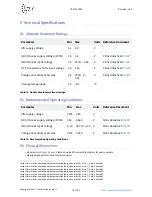
Страница 15: ...e Maximum Ratings Parameter Min Max Units Reference Document VIN supply voltage 0 1 6 0 V HR I O banks supply voltage VCCO 0 5 3 6 V Xilinx datasheet DS1813 HR I O banks input voltage 0 4 VCCO 0 55 V...

Страница 16: ...shop trenz electronic de de Download path Trenz_Electronic TE0714 PCB thickness 1 6 mm Highest part on PCB approximately 2 5 mm Please download the step model for exact numbers All dimensions are show...

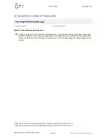
Страница 17: ...x 7 TE0714 Artix 7 10 Variants Currently In Production Trenz shop TE0714 overview page English page11 German page12 Table 14 Trenz Electronic Shop Overview On REV 01 JM2 Pin 54 was connected to GND Wh...

Страница 18: ...Hardware Revision History Date Revision PCN Documentation Link Note 2016 08 04 02 PCN 2016081513 TE0714 0214 VCCIO0 added to B2B 01 TE0714 0115 Table 15 Hardware Revision History Hardware revision nu...

Страница 19: ...lash PCN Corrected table headings 2018 09 17 v 36 Martin Rohrm ller Update to TRM version 2 0 with DrawIO Figures Added Figure Power Distribution 2018 04 04 v 35 Martin Rohrm ller Corrected clock net...

Страница 20: ...Electronic GmbH 20 of 22 http www trenz electronic de 24 https wiki trenz electronic de display s kunath 25 https wiki trenz electronic de display tht Date Revision Authors Description Kunath24 Thors...

Страница 21: ...ny damages whatsoever including without limitation those resulting from lost profits lost data or business interruption arising out of the use inability to use or the results of use of this document a...

Страница 22: ...European Union in accordance with Directive 2002 96 EC of the European Parliament and of the Council of 27 January 2003 on waste electrical and electronic equipment WEEE Users of electrical and electr...

Отзывы: