


TMM4500 Reference Guide
Chapter 3 - Installation Instructions
B
EFORE
Y
OU
B
EGIN
We suggest you power the unit up and confirm it functions correctly and that nothing was
damaged in shipping.
We suggest you power the unit up and confirm it functions correctly and that nothing was
damaged in shipping.
CAUTION
Do not remove the cover or back of your new equipment. There are
no user serviceable parts inside. Contact
Trenton Systems technical
support
if you need assistance.
R
ACK
M
OUNTING
The TRC4012 system can be installed in a rackmount cabinet that conforms to EIA standards for computer
equipment with 19-inch wide panels. The cabinet must be tall enough to accommodate the computer’s
height and deep enough to accommodate the system’s depth, while providing the proper clearances for air
flow and cabling. A cabinet with a standard depth of 31.5 inches (800mm) should be sufficient; however, a
rack with a non-standard depth dimension of at least 22 inches (559mm) will provide the suggested
minimum front and rear chassis clearances needed for an installation.
The TRC4012 is designed to be supported in the cabinet with rack slides or placed on a cabinet shelf. The
front flanges of the computer are designed to secure the TRC4012 to the rack cabinet’s front mounting rails
R
ACKMOUNT
I
NSTRUCTIONS
A)
Determine the mounting location within the rack and mark the mounting holes in the front and
rear of the rack enclosure accordingly (this is for easy reference while you are mounting the equipment).
NOTE
If installing by yourself or even with a helper, just below where you are going to mount the unit
install 2 of the 10-32 screws (or M6 if using an alternate rack) in the front mounting surface leaving at
least 1/4” inch of thread exposed. This will act as a wrest to assist holding the unit in place when
installing the unit.
B)
Install the rear “L” mounting brackets to the rear face of the enclosure using 4x 10-32 Panhead
Screws set at the desired height/location.
C)
Find the target installation depth by measuring the front face/mounting surface of the rack to
center- line of the mounting hole of the rear “L” mounting bracket.
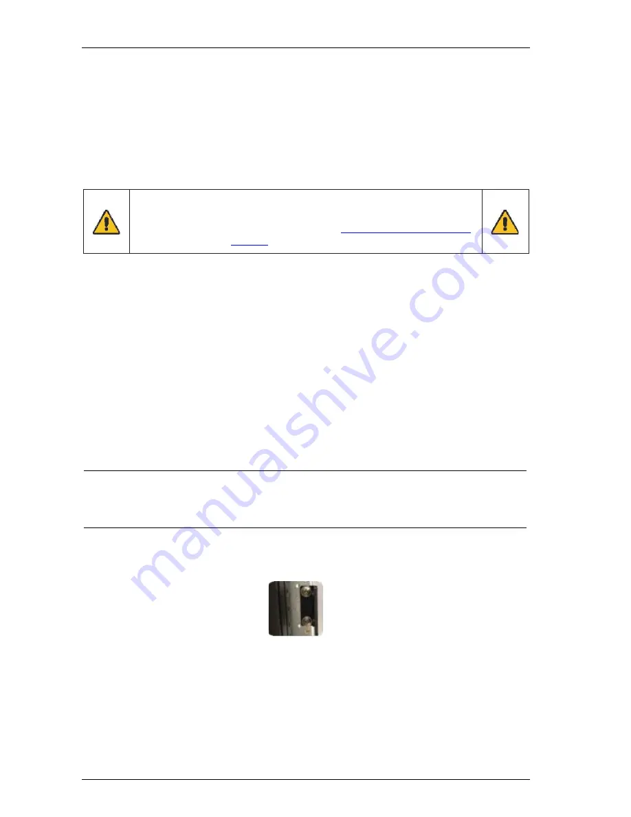
D)
The measurement from the front ear to the rear arms elongated mounting holes must be the same
length as step 3. Some adjustment of the aluminum support arms is likely needed ensure a proper fit. To
adjust the arms use the Hex Head tool to loosen or remove the Pancake screws as necessary until the
elongated holes of the arms match the measurement. Once at the correct measurement then once again
secure the arms in place.
3-1
Trenton Systems, Inc.


