MBS1000 Installation Guide
3-3
Trenton Systems, Inc.
Slide Rail Installation (continued)
6.
Attach the end of the rack slide with the two-hole bracket and the 1U component rack mounting
ears toward front of the rack as shown in Figure 3B.
a.
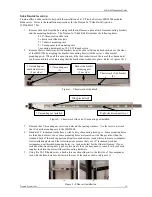
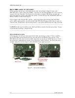
Referring to Figure 4, adjust the hex nuts on the back side of each rack slide as necessary
for the required component rack depth.
b.
Note: leave all slide mounting screws and depth-adjustment hex nuts until step 15.
Figure 4 – Slide rail depth adjustments
11.
Repeat steps 4 and 5 for the right side slide rail referring to figures 3A, 3B and 4 as necessary.
12.
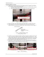
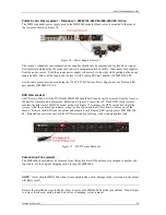
If the mounting holes for you particular component rack are on the inside portions of your
rackmount supports, then mount each assembly directly to the rack supports as shown in figure 5.
13.
CAUTION – Ensure that when mounting the completed rail and frame assemblies to the 19” rack
that the left and right assemblies are the same distance from the top or bottom of the rack. Failure
to align the slide rails properly will result in the modular blade server binding when moving in and
out of the component rack or not being level inside the rack. If the slides are grossly misaligned
then you may not be able to slide the chassis into the slide rails.
14.
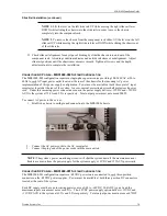
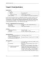
Refer to figure 6. Extend the slide rails to their maximum setting until they lock into position.
Slide the chassis into the rails attached to the frame of the rackmount enclosure. (You should have
another person help you lift and slide the chassis into the enclosure.)
Figure 5 – Rail/Frame Mounting – Inside
Rackmount Hole Locations
Figure 6 – Chassis Installation
Slide rail depth-adjustment hex nuts
(4 per rack slide)
Right-side disconnect lever
Left-side disconnect lever


