2. How to Install
2
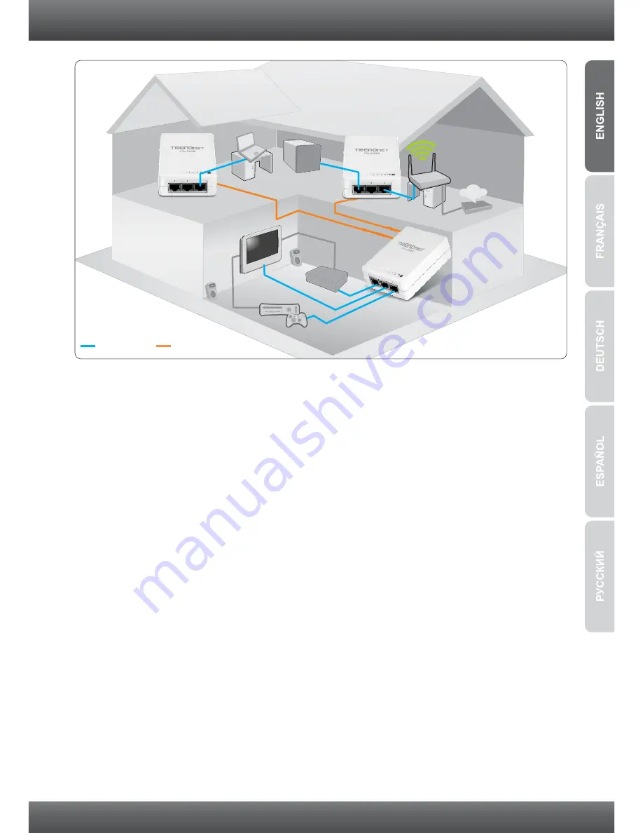
The example diagram shows a typical powerline network configuration in a home
environment with 3 powerline adapters installed in different rooms. The orange line
represents the powerline connectivity established through your home's electrical system
and the blue lines represent Cat. 5, 5e, 6 Ethernet connectivity to your network enabled
appliances such as a computer, router, or IP set top box connected to your television.
Note:
1. DO NOT install the TPL-305E until instructed to do so
2. DO NOT plug the TPL-305E into a surge protector or power strip.
3. Avoid connecting the TPL-305E into an outlet that has appliances
(e.g. refrigerators, washer and dryer) plugged in.
4. In order for the TPL-305E to link to each other, each unit must be on the same
electrical system.
5. A maximum of 16 TPL-305E can be networked.
6. Assuming that the TPL-305E are configured with the default settings, to create
a powerline network, simply connect all TPL-305E adapters to wall outlets that
are on the same electrical system. No additional configuration in the utility is
necessary.
7. The network name must be the same on all powerline adapters in order to
establish connectivity. If the network name is not the same on all powerline
adapters, the adapters will NOT establish connectivity. The default network
name for the TPL-305E is “HomePlugAV”.
3-Port 200Mbps Powerline AV Adapter
(TPL-305E)
10/100Mbps
Powerline
Internet
Game Console
Media
Server
Wireless
Router
Storage
X
Y
B
A
X
Y
B
A
Содержание TPL-305E
Страница 1: ...Quick Installation Guide TPL 305E 1 01 ...
Страница 7: ...5 3 LEDs and Buttons 1 3 Ethernet PWR Power Reset Button Sync PL Powerline ...
Страница 11: ......
Страница 13: ...Copyright 2011 All Rights Reserved TRENDnet ...


